

 Free US Calls: 1-888-433-4735
 International: 305-545-5588
This comprehensive FAQ addresses common questions and provides detailed insights about the Detroit Diesel 71 Series Inline Engines (271, 371, 471, 671), as detailed in the service manual.
General Information For Detroit Diesel 71 Series Inline Engines (271, 371, 471, 671) FAQ
What is covered in this manual?
The manual provides comprehensive information for servicing, maintaining, and overhauling Detroit Diesel 71 Series Inline Engines. It includes instructions on operation, adjustments (tune-ups), preventive maintenance, lubrication, and complete overhauls. Volume 2 of the Detroit Diesel 71 Series Inline Engine Service Manual provides detailed instructions on operation, maintenance, troubleshooting, and overhaul procedures for critical systems, including the lubrication, cooling, air, and fuel systems, as well as specifications and assembly guidance for engine components.
Which engines are included in the 71 Series Inline?
The manual covers 271, 371, 471, and 671 models. These engines are available in various configurations for marine, industrial, and vehicle applications.
Maintenance and Operation For Detroit Diesel 71 Series Inline Engines (271, 371, 471, 671) FAQ
What type of oil should I use for lubrication?

Use heavy-duty oil suitable for diesel engines, meeting the API service classifications specified for Detroit Diesel engines. Key factors include:
- Viscosity Grade:
- Cold Climates: SAE 10W or 15W-40 for improved cold-start lubrication.
- Moderate to Hot Climates: SAE 30 or SAE 40 for enhanced protection at higher operating temperatures.
- Additional Considerations:
- Select oils with high detergency to reduce sludge and varnish buildup.
- Ensure anti-wear additives are present to protect critical components such as camshafts and bearings.
How often should I change the oil?

Change engine oil and oil filter elements based on:
- Manufacturer Recommendations: Follow suggested intervals for operating hours or mileage.
- Oil Condition: Replace oil earlier if it appears degraded, excessively dark, or contains unusual debris.
- Severe Service Use: Engines exposed to dusty environments, high-load operation, or extreme conditions may require more frequent oil changes.
What are the daily checks recommended for optimal performance?
Perform these checks daily to maintain engine reliability and performance:
- Coolant System:
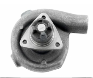
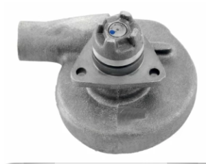
Water Pump for Detroit Diesel engine 6-71 turbo
- Verify the coolant level is at the recommended mark.
- Inspect for leaks or residue around hoses, connections, and the radiator.
- Oil Levels:
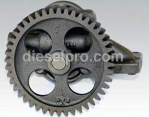
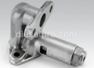
Right Hand Oil Pump – Used In Detroit Diesel 371, 471, and 671 Engines
- Check the oil level using the dipstick and maintain it between the “full” and “low” marks.
- Inspect for oil leaks around the pan, filter housing, and seals.
- Fuel System:
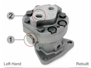
Detroit Diesel Fuel Pump – Left-Hand
- Examine fuel connections for leaks or signs of wear.
- Ensure the fuel tank vent is unobstructed.
- Air Filters:
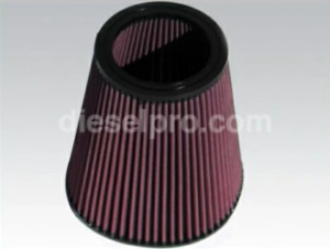
Filter for Detroit Diesel Engine 671
- Inspect air filters for dirt and clogging.
- Clean or replace filters as necessary to maintain airflow and prevent contaminants from entering the engine.
- General Inspection:
- Look for loose bolts or connections on major components.
- Check the belt tension on accessories like the alternator or water pump.
- Inspect for abnormal noises or vibrations during operation.
Regular adherence to this checklist will help prevent unexpected failures and prolong the life of the engine.
How often should I replace the oil filter?
- Routine Replacement: Replace the oil filter every time the oil is changed to maintain optimal engine performance and prevent contamination. Regular replacement ensures proper filtration and extends engine life.
- Severe Conditions: For engines operating in dusty or high-load environments, consider more frequent replacements as oil contamination can occur faster.
- Clogged Filter Signs: If oil pressure fluctuates or drops, it could indicate a clogged filter. Immediate replacement is necessary to prevent bypass valve activation, which allows unfiltered oil to circulate.
How can I check the oil level properly?
- Engine Off: Always check the oil level when the engine is off to ensure accurate readings.
- Wait for Drain Back: Allow the engine to rest for at least 20 minutes to enable oil to drain back into the pan from the various engine components.
- Use the Dipstick:
- Remove the dipstick and wipe it clean.
- Reinsert the dipstick fully and withdraw it to check the oil level. Ensure it is between the “low” and “full” marks.
- Avoid Overfilling: Overfilling can cause oil foaming, leading to high oil temperatures, leaks, and aeration, which reduces lubrication efficiency.
- Inspection Tip: Regularly inspect the dipstick for discoloration or debris, as these can indicate contamination or potential issues with the lubrication system.
What should I do if the lubrication system becomes contaminated?
- Signs of Contamination: Look for symptoms such as discolored oil, sludge buildup, or unusual odors. These may indicate coolant leaks, dirt ingress, or other contaminants.
- Immediate Actions:
- Drain the Oil: Completely drain the contaminated oil from the engine.
- Replace the Oil Filter: Install a new filter to prevent residual contaminants from reentering the system.
- Flush the System: Use a cleaning solution or flush as recommended in the service manual to remove all traces of contaminants.
- Inspect for Damage: Check components such as the oil cooler and pump for potential sources of contamination.
- Preventative Measures: Regularly check for leaks or signs of wear in components like the oil cooler core, which could allow coolant or debris to enter the system.
How do I maintain proper oil quality in my engine?
- Use the Correct Oil Grade: Always use oil with the recommended viscosity and grade for your engine’s operating conditions.
- Monitor Oil Condition: Regularly inspect the oil for discoloration, sludge, or metallic particles that indicate wear or contamination.
- Change Oil Regularly: Follow the oil change intervals recommended by the oil supplier and engine manual, adjusting for operating conditions.
- Store Oil Properly: Ensure the oil is stored in a clean, dry environment to avoid contamination before use.
When should I replace the oil cooler?

- Leaking Oil Cooler: Replace the oil cooler if it shows signs of leakage, as it can lead to cross-contamination of oil and coolant.
- Clogged Core: If the oil cooler core becomes clogged and cleaning does not restore normal flow, replacement is required to prevent engine overheating.
- Regular Inspections: Include the oil cooler in routine maintenance checks to identify potential issues early.
Cylinder Block and Head For Detroit Diesel 71 Series Inline Engines (271, 371, 471, 671) FAQ
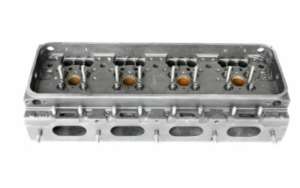
What are the cylinder head tightening specifications?
To ensure proper sealing and prevent leaks, follow these steps for tightening the cylinder head bolts:
- Preparation:
- Clean the threads of all bolts and the corresponding holes in the block to ensure accurate torque readings.
- Apply a small amount of International Compound No. 2 or an equivalent anti-seize compound to the bolt threads and under the bolt heads.
- Tightening Sequence:
- Tighten the bolts in the specified sequence outlined in the manual to evenly distribute clamping forces and prevent head distortion.
- Begin with the bolts closest to the center and work outward in a crisscross pattern.
- Torque Settings:
- Tighten in increments:
- First pass: 50 lb-ft (68 N-m).
- Second pass: 120 lb-ft (163 N-m).
- Final pass: 170–180 lb-ft (231–244 N-m).
- Recheck all bolts in sequence after completing the final pass to ensure proper torque.
- Tighten in increments:
How do I inspect cylinder block bores for wear?

- Initial Cleaning:
- Clean the bores thoroughly to remove any carbon deposits or oil residue that may affect measurements.
- Clean the bores thoroughly to remove any carbon deposits or oil residue that may affect measurements.
- Measurement Points:
- Measure each bore at six points:
- Two measurements each at the top, middle, and bottom of the bore.
- Orient the measurements at 90° angles to capture both longitudinal and transverse wear.
- Measure each bore at six points:
- Tools Required:
- Use a cylinder bore gauge capable of measuring in increments of 0.0001 inches for accuracy.
- Zero the bore gauge using a master ring gauge before taking measurements.
- Common Wear Patterns:
- Taper: The bore is wider at one end, typically the top, due to wear from piston travel.
- Out-of-Round: Uneven wear caused by forces acting differently in various directions.
- Acceptable Limits:
- Consult the manual for specific tolerances. Typically, taper or out-of-round exceeding 0.002 inches may require rebore and fitting with oversized liners.
- Consult the manual for specific tolerances. Typically, taper or out-of-round exceeding 0.002 inches may require rebore and fitting with oversized liners.
How can I check the flatness of the cylinder head?

- Preparation:
- Clean the cylinder head surface thoroughly to remove debris, carbon deposits, or gasket material.
- Clean the cylinder head surface thoroughly to remove debris, carbon deposits, or gasket material.
- Tools Required:
- Use a heavy-duty, precision straight edge and feeler gauges.
- Use a heavy-duty, precision straight edge and feeler gauges.
- Measurement Procedure:
- Place the straight edge across the cylinder head in multiple locations:
- Transverse (width): At the ends and across all cylinder positions.
- Longitudinal (length): At the center and near both edges.
- Insert feeler gauges between the straight edge and the cylinder head surface to determine the gap.
- Place the straight edge across the cylinder head in multiple locations:
- Maximum Allowable Warpage:
- 3-71 Engines: 0.0055 inches (longitudinal), 0.004 inches (transverse).
- 4-71 Engines: 0.008 inches (longitudinal), 0.004 inches (transverse).
- 6-71 Engines: 0.010 inches (longitudinal), 0.004 inches (transverse).
- Corrective Actions:
- If warpage exceeds limits, the cylinder head may need to be resurfaced. Ensure the minimum thickness of the head is maintained to avoid interference with valves or piston travel.
- If warpage exceeds limits, the cylinder head may need to be resurfaced. Ensure the minimum thickness of the head is maintained to avoid interference with valves or piston travel.
- Post-Check Requirements:
- Inspect the head gasket surface for signs of leaks or uneven wear.
- Recheck measurements after resurfacing to confirm the head meets specifications.
Adhering to these procedures ensures a proper seal between the cylinder block and head, minimizes the risk of compression leaks, and maintains overall engine performance.
Lubrication System For Detroit Diesel 71 Series Inline Engines (271, 371, 471, 671) FAQ
What components make up the lubrication system?
The lubrication system ensures consistent oil flow to critical engine components, reducing wear and managing temperature. Key components include:
- Oil Pump:
- A gear-type pump mounted on the main bearing caps, driven by the crankshaft.
- Draws oil from the sump and pressurizes it for circulation throughout the engine.
- Full-Flow Oil Filters:
- Located between the oil pump and the cooler, these filters ensure that all oil entering the engine is clean.
- Equipped with bypass valves that allow oil to flow directly to the cooler if the filter becomes clogged.
- Pressure Regulator Valve:
- Stabilizes oil pressure within the engine by diverting excess oil back to the sump when pressure exceeds 50 psi (345 kPa).
- Maintains optimal pressure across all operating speeds and temperatures.
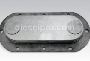
- Oil Cooler:
Oil Cooler For Detroit Diesel 671 Engines
- Lowers oil temperature to prevent overheating and maintain its viscosity.
- Located in the cooling system, often in the expansion tank for water-cooled engines or near the radiator for air-cooled systems.
- Bypass Filter (Optional):
- Filters a small portion of the oil continuously, removing finer particles.
- Returns cleaned oil to the sump.
- Oil Pan and Dipstick:
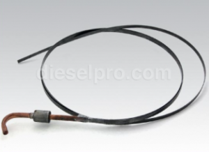
Dipstick for Detroit Diesel engine 72″ long
- The oil pan stores the engine’s oil supply.
- The dipstick allows users to monitor oil levels.
How do I troubleshoot low oil pressure?
Low oil pressure can severely damage engine components. To identify and address the issue:
- Inspect the Oil Pump:
- Remove and disassemble the oil pump.
- Check the gears, shafts, and bushings for wear or scoring.
- Ensure the pump relief valve moves freely and seals properly.
- Examine the Pressure Regulator Valve:
- Remove the valve and inspect for obstructions or wear.
- Clean and replace worn components as necessary.
- Reinstall and ensure it maintains proper pressure.
- Verify Oil Viscosity and Cleanliness:
- Check the oil level and ensure it matches the recommended grade for ambient temperatures.
- Drain and replace oil if contamination (e.g., sludge, coolant, or debris) is detected.
- Check for Leaks:
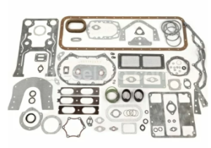
Overhaul gasket kit for Detroit Diesel engine 6-71
- Inspect seals, gaskets, and connections throughout the system.
- Tighten or replace components as needed.
- Inspect the Bearings:
- Excessively worn main or rod bearings can cause oil pressure drops. If pressure remains low after addressing the pump and regulator, inspect these components.
- Excessively worn main or rod bearings can cause oil pressure drops. If pressure remains low after addressing the pump and regulator, inspect these components.
What should I do if the oil cooler is clogged?
A clogged oil cooler can lead to excessive engine temperatures and reduced lubrication efficiency. Follow these steps:
- Identify the Problem:
- Monitor oil temperatures. Consistently high readings may indicate a clogged cooler.
- Check for oil pressure drops, as restricted flow through the cooler can affect the system.
- Inspect the Cooler:
- Remove the oil cooler and visually inspect for blockages or damage.
- Check the bypass valve for proper operation. This valve ensures oil can flow directly to the engine if the cooler becomes clogged.
- Clean the Cooler:
- Use a trichloroethylene or alkaline solution to dissolve sludge and debris on the oil side.
- Flush thoroughly with clean hot water.
- Pressure Test the Cooler:
- Submerge the cooler in a tank of hot water.
- Apply 75–150 psi (517–1,034 kPa) of air pressure and look for leaks indicated by bubbles.
- Replace the Cooler:
- If leaks are detected or cleaning is unsuccessful, replace the oil cooler with a new unit to prevent contamination or oil starvation.
- If leaks are detected or cleaning is unsuccessful, replace the oil cooler with a new unit to prevent contamination or oil starvation.
- Prevent Future Clogging:
- Regularly change oil and filters to minimize sludge buildup.
- Avoid operating the engine under extreme conditions without proper maintenance.
Proper maintenance of the lubrication system ensures longevity and efficient operation of your Detroit Diesel 71 Series Inline Engine. Routine inspections and timely interventions can prevent major failures and costly repairs.
What components are covered in Volume 2?
Volume 2 provides a comprehensive guide to the lubrication system of Detroit Diesel 71 Series Inline Engines. It covers the following components in detail:
- Oil Pump: Describes the gear-type oil pump mounted on the main bearing caps, its function, and maintenance. It includes the integral relief valve, which regulates oil flow under varying pressure conditions. Specific guidelines for disassembly, inspection, and reassembly are included.
- Lubricating Oil Pressure Regulator: Covers the mechanism that ensures stabilized oil pressure regardless of oil temperature or engine speed. Details include troubleshooting pressure fluctuations and maintenance of the spring-loaded valve system.
- Lubricating Oil Filters: Discusses both full-flow and bypass oil filters. The manual emphasizes the importance of the full-flow filter, which cleans all oil entering the engine, and optional bypass filters for enhanced filtration.
- Oil Cooler: Explains its function in maintaining the oil’s temperature. Details include its mounting on various engine types, the integrated bypass valve, and servicing instructions like cleaning and pressure testing.
- Oil Level Dipstick: Highlights its role in monitoring proper oil levels, along with procedures for accurate readings to avoid overfilling or underfilling.
- Oil Pan: Explains the variations (shallow or deep sump) based on engine inclination and its role in storing and delivering oil. Maintenance includes proper cleaning, gasket replacement, and torque specifications for reassembly.
Why is the oil cooler important?
The oil cooler is a vital component of the lubrication system, ensuring the engine oil operates within its ideal temperature range. Specific benefits include:
- Prevention of Overheating: When engine oil becomes too hot, its viscosity decreases, reducing its ability to protect engine components and support bearing loads. The cooler dissipates excess heat to prevent this.
- Support for Cold Starts: During low temperatures, oil may thicken, reducing its flow efficiency. The oil cooler ensures optimal viscosity for proper lubrication even in cold weather.
- Integrated Bypass Valve: If the cooler becomes clogged, the bypass valve ensures continued oil flow directly to the oil gallery, preventing engine damage.
- Cooling Functions: Heat absorbed during lubrication and piston cooling is transferred to the oil. By using the engine’s cooling system, the oil cooler dissipates this heat effectively, maintaining consistent engine performance.
Volume 2 includes detailed servicing instructions, such as flushing, cleaning, and pressure testing of the oil cooler core. It also emphasizes careful assembly with the correct gaskets and bolt torques to prevent leaks.
How does the oil pump function in these engines?
The oil pump is gear-driven and forces oil through the full-flow filter, cooler, and galleries to ensure proper lubrication of engine components.
-
What is the standard oil pressure?
The oil pressure regulator maintains a normal operating pressure of 50 psi (345 kPa). If the pressure exceeds 105 psi (724 kPa), the relief valve bypasses excess oil.
-
How do I maintain the oil pump?
Regularly clean the inlet screen and inspect the gears for wear. Replace components if excessive wear or damage is found to avoid low oil pressure.
Fuel System For Detroit Diesel 71 Series Inline Engines (271, 371, 471, 671) FAQ
How do I replace a fuel injector?

Replacing a fuel injector is a straightforward process but requires attention to detail to ensure proper installation and functionality. Follow these steps:
- Preparation:
- Ensure the engine is off and cool.
- Disconnect the battery to prevent accidental starts.
- Clean the area around the injector to prevent debris from entering the fuel system.
- Disconnect the Fuel Pipes:
- Loosen the nuts securing the fuel pipes to the injector and fuel manifold.
- Carefully remove the pipes, ensuring not to bend or damage them. For flared-end pipes, avoid reusing them if deformed.
- Remove the Injector Clamp Bolts:
- Using a torque wrench or breaker bar, remove the bolts holding the injector clamp in place.
- Retain the clamp and bolts for reuse unless damaged.
- Extract the Injector:
- Use a specialized injector removal tool to avoid damaging the injector or cylinder head.
- Gently rock the injector side-to-side while pulling upward to loosen it.
- Inspect and Clean the Injector Seat:
- Examine the injector seat for carbon deposits or damage.
- Use a soft brush or a reaming tool to clean the seat, ensuring a smooth surface for the new injector.
- Install the New Injector:
- Apply a light coat of engine oil or fuel to the O-rings or sealing surfaces of the new injector.
- Place the injector into the seat, ensuring it aligns correctly with the fuel manifold and cylinder head.
- Secure the Injector:
- Position the clamp over the injector and tighten the clamp bolts in stages.
- Torque the bolts to the manufacturer’s recommended value, typically 20–25 lb-ft (27–34 N-m).
- Reconnect the Fuel Pipes:
- Align the fuel pipes carefully and hand-tighten the nuts.
- Use a torque wrench to secure the connections to prevent leaks. Over-tightening can damage the fittings.
- Bleed the Fuel System:
- Prime the system using the fuel pump or priming lever to remove air pockets.
- Follow the manufacturer’s guidelines for bleeding procedures.
- Test the Installation:
- Start the engine and inspect for leaks around the injector and fuel lines.
- Address any leaks immediately by retightening or replacing components.
How do I test the fuel system for leaks?
Ensuring a leak-free fuel system is crucial for engine performance and safety. Perform the following steps to test for leaks:
- Prepare the System:
- Clean all connections to remove any oil, dirt, or fuel residue that could mask a leak.
- Verify that the fuel system is properly primed and pressurized.
- Pressurize the Fuel System:
- Use the fuel pump to build pressure in the system.
- For engines equipped with a manual priming pump, operate it until resistance is felt, indicating pressure buildup.
- Inspect Visually:
- Observe all fuel line connections, injector seals, and filter housings for signs of leakage.
- Look for fuel drips, wet spots, or a strong fuel odor, which may indicate a leak.
- Focus on Key Areas:
- Check injector connections for proper sealing.
- Inspect the fuel filter housing for cracks or loose fittings.
- Examine fuel line bends and clamps for wear or looseness.
- Use a Leak Detection Solution:
- Apply a soap-and-water solution to suspected leak points.
- Watch for bubbles forming, indicating a leak.
- Test Under Operating Conditions:
- Start the engine and let it idle while rechecking for leaks.
- Increase the engine speed slightly to simulate higher pressure and load.
- Address Any Leaks:
- Tighten connections to the specified torque.
- Replace faulty components, such as fuel pipes, clamps, or seals.
- Verify Repairs:
- Repeat the pressurization and inspection steps to ensure the system is leak-free.
- Repeat the pressurization and inspection steps to ensure the system is leak-free.
Cooling System For Detroit Diesel 71 Series Inline Engines (271, 371, 471, 671) FAQ
How does the cooling system work?
The cooling system in the Detroit Diesel 71 Series Inline Engines operates to maintain optimal engine temperature and prevent overheating. Here’s how it works:
- Coolant Circulation:
- A centrifugal water pump draws coolant from the radiator or heat exchanger and circulates it through the engine block and cylinder head.
- The coolant absorbs heat from the engine and carries it back to the radiator or heat exchanger, where it is cooled before recirculation.
- Thermostat Function:
- The thermostat regulates coolant flow based on engine temperature.
- When the engine is cold, the thermostat remains closed, allowing the coolant to circulate within the engine to quickly reach operating temperature.
- As the engine warms up, the thermostat opens to direct coolant through the radiator or heat exchanger.
- Heat Dissipation:
- In radiator-cooled systems, the fan pulls air through the radiator to dissipate heat from the coolant.
- In marine applications, a heat exchanger transfers heat from the engine coolant to seawater.
- Auxiliary Components:
- The system includes hoses, fittings, and temperature sensors to ensure proper flow and monitoring.
- A pressure cap on the radiator or heat exchanger maintains the system’s pressure to raise the boiling point of the coolant and prevent vapor formation.
How can I clean and flush the cooling system?
A clean and well-maintained cooling system ensures efficient operation and prolongs engine life. Follow these steps to clean and flush the system:
- Preparation:
- Ensure the engine is off and cool before starting the procedure.
- Place a drain pan under the engine to collect the used coolant.
- Drain the Coolant:
- Open the radiator or heat exchanger drain valve and the block drain plugs to fully drain the coolant.
- Dispose of the coolant according to local environmental regulations.
- Add Cleaning Solution:
- Refill the system with a commercial radiator cleaner or a mixture of water and a mild cleaning agent (e.g., vinegar or baking soda).
- Follow the cleaner manufacturer’s instructions for concentration and operation time.
- Operate the Engine:
- Start the engine and let it run at operating temperature for 15–30 minutes to allow the cleaner to dissolve scale, rust, and deposits.
- Start the engine and let it run at operating temperature for 15–30 minutes to allow the cleaner to dissolve scale, rust, and deposits.
- Flush the System:
- Drain the cleaning solution completely.
- Refill the system with clean water and run the engine briefly to flush out any remaining contaminants.
- Repeat the flushing process until the drained water is clear.
- Refill with Coolant:
- Use a 50/50 mixture of antifreeze and distilled water unless otherwise specified.
- Fill the system slowly to avoid air pockets.
- Bleed the System:
- Open the bleed valve, if equipped, to release trapped air.
- Ensure the system is fully topped off after bleeding.
- Inspect for Leaks:
- Run the engine and check all hoses, clamps, and connections for leaks.
- Run the engine and check all hoses, clamps, and connections for leaks.
What should I do if the engine overheats?
Overheating can cause severe engine damage. Take these steps to identify and resolve the issue:
- Stop the Engine:
- Immediately turn off the engine to prevent further damage.
- Allow the engine to cool completely before inspecting the system.
- Check for Coolant Leaks:
- Look for signs of leaks around hoses, clamps, the radiator, and the engine block.
- Inspect the coolant reservoir for proper levels.
- Inspect the Radiator or Heat Exchanger:
- Check for external blockages such as debris or dirt.
- Ensure that the radiator fins or heat exchanger tubes are clean and unobstructed.
- Verify Fan Operation:
- Check if the fan is turning at the correct speed.
- Inspect the fan belt for tension, wear, or breakage.
- Test the Thermostat:
- Remove and test the thermostat in hot water to ensure it opens at the correct temperature.
- Replace it if it fails to operate properly.
- Examine the Water Pump:
- Inspect for wear, leaks, or loose connections.
- Verify that the pump is circulating coolant effectively.
- Check for Airlocks:
- Bleed the system to remove trapped air, which can impede coolant flow.
- Bleed the system to remove trapped air, which can impede coolant flow.
- Restart the Engine:
- Refill the system with coolant and start the engine.
- Monitor the temperature gauge to ensure it stays within normal operating range.
Exhaust Valves and Guides For Detroit Diesel 71 Series Inline Engines (271, 371, 471, 671) FAQ
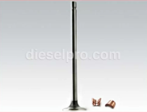
How do I replace exhaust valves and guides?
Replacing exhaust valves and guides is a detailed process that ensures optimal engine performance and longevity. Follow these steps:
- Preparation:
- Ensure the engine is off and cool before beginning.
- Disconnect the battery to prevent accidental starts.
- Remove all necessary components obstructing access to the cylinder head, including the air intake, exhaust manifold, and fuel lines.
- Remove the Cylinder Head:
- Drain the coolant and lubricating oil from the engine.
- Disconnect all attachments to the cylinder head, such as injector lines, rocker arms, and brackets.
- Use a lifting tool to remove the cylinder head and place it on a clean workbench with protective padding.
- Disassemble the Valve Mechanism:
- Use a valve spring compressor to compress the valve springs.
- Remove the valve keepers, springs, and retainers, ensuring parts are stored in an organized manner.
- Extract the Valves:
- Slide the valves out of their guides, inspecting them for wear, scoring, or damage.
- Discard valves that do not meet the specifications outlined in the manual.
- Remove the Valve Guides:
- Use a valve guide removal tool or a drift punch to drive out the old guides from the cylinder head.
- Inspect the guide bore for damage or excessive wear. Reconditioning may be required if out of tolerance.
- Install New Valve Guides:
- Clean the guide bore thoroughly.
- Heat the cylinder head to facilitate the installation of press-fit guides.
- Press the new guides into place using a hydraulic press or installation tool. Ensure they are seated at the correct depth.
- Regrind the Valve Seats:
- Use a valve seat cutter or grinder to recondition the seat to match the new valve’s specifications.
- Check the seat for concentricity, width, and surface finish. Adjust as necessary for a proper seal.
- Reassemble the Valves:
- Lightly coat the valve stems with engine oil.
- Insert the valves into the guides.
- Compress the springs using a valve spring compressor and reinstall the retainers and keepers.
- Double-check that all components are seated correctly.
- Reinstall the Cylinder Head:
- Follow the manufacturer’s specifications for gasket installation and head bolt tightening sequence and torque.
- Reconnect all removed components, refill coolant and oil, and perform an engine tune-up to complete the process.
What are the valve clearance specifications?
Valve clearance plays a crucial role in ensuring efficient engine operation and preventing premature wear or damage. Follow these guidelines:
- Refer to the Manual:
- Consult the tune-up section of the service manual for exact clearance values based on your specific engine model.
- Consult the tune-up section of the service manual for exact clearance values based on your specific engine model.
- General Valve Clearance Settings:
- Intake Valves: Typically set at 0.012–0.014 inches.
- Exhaust Valves: Typically set at 0.024–0.026 inches.
- Always confirm these values with the manual for accuracy.
- When to Check Valve Clearance:
- Check valve clearance during routine tune-ups or when signs of poor performance, such as misfiring or unusual noises, are observed.
- Adjust clearances after reassembling the cylinder head or replacing valve components.
- How to Check Valve Clearance:
- Rotate the engine to bring the piston of the cylinder being checked to Top Dead Center (TDC) on the compression stroke.
- Insert a feeler gauge between the valve stem and rocker arm to measure clearance.
- Adjust the clearance by loosening the locknut and turning the adjustment screw as needed.
- Post-Adjustment Verification:
- Rotate the engine through several cycles and recheck the clearance to ensure consistent settings.
- Tighten all adjustments securely and ensure no binding or misalignment.
Troubleshooting For Detroit Diesel 71 Series Inline Engines (271, 371, 471, 671) FAQ
What causes excessive smoke from the exhaust?
Excessive smoke is often a sign of underlying engine issues. Here’s how to identify and address different types of exhaust smoke:
- Blue Smoke (Oil Burning):
- Causes:
- Worn piston rings allowing oil to enter the combustion chamber.
- Faulty valve seals leaking oil into the cylinders.
- Clogged or malfunctioning crankcase ventilation system.
- Troubleshooting:
- Perform a compression test to check for worn piston rings.
- Inspect valve seals for wear or cracking; replace if necessary.
- Clean or replace the crankcase ventilation components.
- Causes:
- Black Smoke (Incomplete Combustion):
- Causes:
- Clogged air filters restricting airflow.
- Malfunctioning injectors delivering excessive fuel.
- Poor fuel quality or contamination.
- Turbocharger issues (if equipped), such as insufficient boost or leaking seals.
- Troubleshooting:
- Clean or replace the air filters.
- Test and calibrate injectors for proper operation.
- Drain and replace contaminated fuel; clean the fuel system.
- Inspect the turbocharger for proper operation and replace damaged components.
- Causes:
- White Smoke (Coolant or Fuel Issues):
- Causes:
- Coolant entering the combustion chamber due to a blown head gasket or cracked cylinder head.
- Cold engine operation in low ambient temperatures.
- Water contamination in the fuel system.
- Troubleshooting:
- Pressure test the cooling system to identify leaks.
- Inspect the head gasket and cylinder head for damage.
- Replace the fuel with clean, uncontaminated diesel.
- Causes:
How do I detect and repair oil leaks?
Oil leaks can lead to reduced lubrication, overheating, and engine damage. Follow these steps to detect and repair them:
- Detection:
- Use Dye: Add a red dye to the lubricating oil and inspect for leaks using a UV light.
- Visual Inspection: Look for wet or oily areas around seals, gaskets, and connections.
- Inspect the Oil Pan: Check for damage or improperly tightened bolts.
- Common Leak Points:
- Valve cover gaskets.
- Oil pan gasket.
- Front and rear main seals.
- Oil cooler lines and connections.
- Repair:
- Replace worn or damaged seals and gaskets.
- Tighten loose bolts and connections to the manufacturer’s specifications.
- For damaged oil pans or lines, replace the affected component entirely.
- Post-Repair Check:
- Refill the engine oil to the proper level.
- Run the engine and inspect for any remaining leaks.
- Address any residual leaks immediately to prevent further damage.
What are the common causes of engine overheating?
Engine overheating can lead to severe damage if not addressed promptly. Common causes include:
- Low Coolant Levels:
- Check for leaks in the radiator, hoses, and water pump.
- Refill the system with the appropriate coolant mixture.
- Clogged Radiator or Heat Exchanger:
- Debris or corrosion can restrict coolant flow.
- Flush and clean the cooling system to restore efficiency.
- Malfunctioning Thermostat:
- A stuck thermostat can prevent coolant circulation.
- Replace the thermostat if it fails to open or close properly.
- Faulty Water Pump:
- Inspect for leaks or worn impellers.
- Replace the pump if it fails to circulate coolant effectively.
- Fan or Belt Issues:
- Check for loose or damaged fan belts.
- Ensure the fan operates correctly and provides adequate airflow.
Why is the engine hard to start?

Difficulty starting the engine can result from several factors:
- Low Battery Voltage:
- Inspect the battery for charge level and corrosion at terminals.
- Replace or recharge the battery as necessary.
- Faulty Fuel System:
- Check for air in the fuel lines and bleed the system if needed.
- Ensure the fuel pump is functioning and delivering adequate pressure.
- Cold Weather Issues:
- Use an engine block heater in low temperatures.
- Verify the functionality of glow plugs or other cold-start aids.
- Compression Issues:
- Perform a compression test to identify worn piston rings or valves.
- Address any detected compression loss with appropriate repairs.
How do I identify and fix poor engine performance?
Poor engine performance often manifests as a lack of power, rough running, or excessive fuel consumption. Troubleshooting steps include:
- Inspect the Air Intake:
- Ensure the air filter is clean and unobstructed.
- Check for leaks in the intake manifold or connections.
- Test the Fuel System:
- Verify injector spray patterns and flow rates.
- Replace clogged fuel filters and clean fuel lines.
- Check Compression Levels:
- Low compression can result from worn rings, valves, or head gasket failure.
- Address issues by reconditioning or replacing affected components.
- Examine Timing:
- Verify that the injector and valve timing are correctly set.
- Adjust timing according to the manual’s specifications.
-
How do I detect leaks in the lubricating system?
Leaks can often be identified visually or by using a dye test. Engines tested at the factory may have residual red dye, which disperses after a few hours of operation.
- What are the signs of a failing oil pressure regulator?
Common signs include fluctuating oil pressure, excessive sludge buildup, or abnormal bypass valve operation.
- What are the signs of a failing oil pressure regulator?
-
What should I do if oil pressure is too high or too low?
Inspect the oil pump, pressure regulator, and oil cooler for blockages or wear. Replace damaged components to restore normal pressure levels.
Safety and Best Practices For Detroit Diesel 71 Series Inline Engines (271, 371, 471, 671) FAQ

What safety precautions should I follow while servicing the engine?
Servicing heavy-duty diesel engines involves various risks. Following these safety precautions ensures both personal and equipment safety:
- Electrical Safety:
- Disconnect the battery by removing one or both cables to prevent accidental engine starts.
- Avoid touching live electrical components to eliminate the risk of shock.
- Personal Protective Equipment (PPE):
- Safety Glasses: Protects against flying debris, especially during grinding or cleaning operations.
- Gloves: Prevents cuts and exposure to harmful chemicals or hot components.
- Steel-Toe Boots: Reduces the risk of foot injuries from dropped tools or components.
- Hearing Protection: Use earplugs or earmuffs when operating noisy equipment or near running engines.
- Lifting and Handling:
- Use proper lifting equipment, such as engine hoists, spreader bars, and slings rated for the engine’s weight.
- Ensure the lifting device is securely attached and positioned to maintain balance during lifts.
- Never work under a suspended engine or heavy component.
- Work Area Preparation:
- Keep the workspace clean and free of oil spills or clutter to prevent slips and falls.
- Ensure proper ventilation to avoid exposure to harmful fumes, especially during engine testing or cleaning with solvents.
- Engine Safety:
- Before working on a running engine, identify hot surfaces such as the exhaust manifold or turbocharger to avoid burns.
- Avoid loose clothing or jewelry that could get caught in moving parts like fans or belts.
- Use caution when working with compressed air, limiting pressure to prevent injury.
How should I handle components that contain asbestos?
Asbestos-containing materials (ACMs) may be present in older gaskets, seals, or brake linings. Improper handling can release harmful fibers into the air. Follow these guidelines:
- Minimize Dust Generation:
- Avoid grinding, cutting, or sawing ACMs, which can release asbestos fibers.
- Use wet methods to dampen the material before removal to suppress dust.
- Use Proper PPE:
- Wear a respirator rated for asbestos protection (e.g., NIOSH-approved N100 or P100 respirator).
- Use disposable coveralls and gloves to prevent fibers from contaminating clothing.
- Removal Techniques:
- Use hand tools like putty knives to carefully remove gaskets and seals without breaking them.
- Avoid power tools that generate heat or dust.
- Containment and Disposal:
- Place all asbestos waste, including used rags, gaskets, and debris, in sealed, labeled, impermeable bags or containers.
- Dispose of asbestos-containing materials in accordance with local hazardous waste regulations.
- Work Area Cleanup:
- Use a HEPA-filter vacuum to clean the work area. Do not use compressed air or regular vacuums, which can spread fibers.
- Wipe down surfaces with wet cloths or mops to remove residual dust.
- Notification and Training:
- Inform workers about the presence of asbestos and train them on safe handling practices.
- Follow OSHA or local guidelines for asbestos handling in workplaces.
Specifications and Torque Values For Detroit Diesel 71 Series Inline Engines (271, 371, 471, 671) FAQ
What are the main bearing torque specifications?
Main bearing cap bolts are critical for maintaining crankshaft alignment and engine reliability. Follow these steps to ensure proper torque:
- Torque Specifications:
- Tighten the main bearing cap bolts to 165–175 lb-ft (224–238 N-m).
- Apply the specified torque evenly and in stages to prevent distortion of the crankshaft journal.
- Procedure:
- Clean the threads of the bolts and the tapped holes in the block to remove debris and ensure accurate torque application.
- Apply a small amount of assembly lubricant or oil to the threads and under the bolt heads to reduce friction.
- Tighten bolts in a crisscross pattern to distribute clamping forces evenly.
- Inspection:
- After torquing, verify crankshaft rotation by hand. It should turn freely without binding, indicating proper alignment.
- Inspect for any signs of uneven wear or misalignment of the bearing shells.
What are the specifications for piston ring gaps?
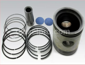
Proper piston ring gaps are essential for maintaining compression, controlling oil consumption, and ensuring overall engine performance. Key considerations include:
- Standard Piston Ring Gap Specifications:
- Compression Rings:
- Top Ring: 0.010–0.020 inches (0.25–0.50 mm).
- Second Ring: 0.010–0.030 inches (0.25–0.75 mm).
- Oil Control Rings:
- 0.015–0.035 inches (0.38–0.88 mm).
- 0.015–0.035 inches (0.38–0.88 mm).
- Compression Rings:
- Procedure for Measuring Ring Gaps:
- Place the piston ring into the cylinder bore and push it down with a piston to ensure it is squarely seated about 1 inch below the top.
- Use a feeler gauge to measure the gap between the ring ends.
- Compare the measurements to the manual’s specified tolerances.
- Adjustments:
- If the ring gap is too tight, carefully file the ends using a ring filer to achieve the correct clearance.
- Avoid excessive filing, as an overly large gap can lead to loss of compression and performance.
- Considerations for New vs. Used Parts:
- New parts will generally adhere to tighter tolerances, while used parts may require allowances for wear.
- Always measure the cylinder bore for out-of-round or taper conditions before finalizing ring gap adjustments.
What are the connecting rod bolt torque specifications?
- Torque Specifications:
- Tighten connecting rod bolts to 45–55 lb-ft (61–75 N-m).
- Use a calibrated torque wrench to ensure accuracy.
- Procedure:
- Lubricate the threads and bolt head contact surfaces to achieve uniform clamping force.
- Tighten bolts incrementally in two to three steps for even pressure distribution.
- Post-Torque Checks:
- Verify that the connecting rod moves freely on the crankshaft after tightening.
- Inspect for any signs of interference or excessive play.
What are the specifications for cylinder liner protrusion?
Cylinder liner protrusion is critical for ensuring proper sealing of the head gasket. The following specifications apply:
- Standard Protrusion:
- Cylinder liners should protrude 0.001–0.004 inches (0.025–0.102 mm) above the engine block deck.
- Cylinder liners should protrude 0.001–0.004 inches (0.025–0.102 mm) above the engine block deck.
- Procedure for Measurement:
- Place a straight edge across the liner and measure the gap between the liner and the block deck using a feeler gauge.
- Check protrusion at multiple points around the liner to ensure uniformity.
- Adjustments:
- If protrusion is insufficient, install shims or replace the liner with one of the correct dimensions.
- Excessive protrusion may require machining or replacement of the liner seat in the block.
Why are torque values critical for engine assembly?
- Preventing Component Failure:
- Correct torque ensures even load distribution, preventing damage to fasteners, gaskets, and mating surfaces.
- Correct torque ensures even load distribution, preventing damage to fasteners, gaskets, and mating surfaces.
- Maintaining Engine Integrity:
- Proper torque values prevent loosening due to vibration and thermal expansion.
- Proper torque values prevent loosening due to vibration and thermal expansion.
- Ensuring Long-Term Performance:
- Adherence to specifications avoids issues such as oil leaks, compression loss, and misalignment, enhancing engine reliability and lifespan.
- Adherence to specifications avoids issues such as oil leaks, compression loss, and misalignment, enhancing engine reliability and lifespan.
Assembly and Tools – For Detroit Diesel 71 Series Inline Engines (271, 371, 471, 671) FAQ
What precautions should I take during reassembly?
- Use New Gaskets and Seals: Always replace gaskets and seals during reassembly. Old gaskets can lose their integrity, leading to leaks and reduced system performance.
- Apply Thread Sealant: Use non-hardening thread sealant on all specified plugs and fasteners. This prevents oil or coolant leakage and ensures a secure fit.
- Follow Torque Specifications: Tighten bolts to the exact torque values outlined in the service manual. Over- or under-tightening can result in component damage or improper sealing.
- Ensure Proper Alignment: During assembly, verify that all components are aligned correctly to avoid stress on the parts and ensure smooth operation. Misalignment can lead to premature wear or failure.
- Inspect Components: Before assembly, clean and inspect all parts for damage or wear. Replace any components that show signs of cracking, scoring, or excessive wear.
- Pre-Lubricate Moving Parts: Apply a thin coat of clean engine oil to bearings, seals, and moving components to reduce friction during initial operation.
- Double-Check Clearances: Measure and confirm that clearances between components, such as the oil pump gears and housing, are within specified limits.
What tools are required for servicing the lubrication system?
- Torque Wrenches: Essential for accurate tightening of bolts to the specified values. Use a calibrated wrench for best results.
- Gear Pullers: Required for safely removing gears during disassembly of the oil pump or other components.
- Arbor Press: Used for precise installation of bushings, bearings, and seals without causing damage.
- Seal Installation Tools: Ensure seals are seated evenly and at the correct depth to avoid leaks.
- Bushing Drivers: Specialized tools for installing or replacing bushings while maintaining proper alignment.
- Feeler Gauges: Used to measure clearances, such as those between oil pump gears and housing.
- Cleaning Equipment: Ultrasonic cleaners, brushes, and fuel oil for cleaning components during maintenance.
- Pressure Testing Tools: Tools for testing the oil cooler and pump components for leaks or blockages.
What should I know about gasket installation?
- Surface Preparation: Ensure all mating surfaces are clean, dry, and free of debris or oil residue before installing gaskets.
- Check Gasket Fit: Verify the gasket matches the component it is sealing. Misaligned gaskets can cause leaks or improper sealing.
- Use Adhesive Sparingly: If specified, use a light adhesive to hold gaskets in place during assembly. Avoid excess adhesive, as it can clog oil passages.
- Compression Check: Once installed, confirm that the gaskets compress evenly and are not pinched or over-compressed.
How can I avoid common assembly mistakes?
- Recheck Torque Values: Use a torque wrench to verify all fasteners meet the required specifications.
- Prevent Over-Tightening: Excessive force can strip threads or distort components.
- Account for Missing Parts: Double-check that all components, seals, and fasteners are accounted for during reassembly.
- Align Components Properly: Misaligned components can result in noise, vibration, or premature wear.
Why is pre-lubrication important during assembly?
- Reduces Wear: Pre-lubrication protects moving parts during initial startup when oil circulation has not yet been established.
- Prevents Galling: Applying a light coat of oil or assembly grease prevents galling or scoring of metal components during assembly.
- Ensures Smooth Operation: Proper lubrication minimizes friction and helps components seat properly during the break-in period.
How do I pressure-test the lubrication system components?
- Oil Cooler Testing: Use a pressure-testing kit to verify that the oil cooler is free of leaks. Submerge the cooler in water and apply air pressure (typically 75-150 psi). Look for escaping bubbles to identify leaks.
- Pump Pressure Testing: Assemble the pump and connect it to a pressure gauge. Ensure the pump produces the required pressure according to the service manual specifications.
- Seal Leak Test: After reassembly, perform a static pressure test by filling the system with oil and pressurizing it to check for leaks at seals and gaskets.
How should tools be maintained for optimal performance?
- Clean After Use: Remove dirt, oil, and debris from tools after each use. This ensures accurate performance and extends their lifespan.
- Calibrate Regularly: Calibrate torque wrenches and pressure-testing gauges periodically to maintain precision.
- Inspect for Wear: Check for worn or damaged tools and replace them if necessary. Tools in poor condition can cause inaccurate readings or damage components.
- Store Properly: Keep tools in a clean, dry environment to prevent rust and corrosion.