

 Free US Calls: 1-888-433-4735
 International: 305-545-5588
Introduction
Proper installation of the Twin Disc MG5050 Marine Gear is essential to ensuring optimal performance, durability, and reliability in marine applications. A poorly installed transmission can lead to misalignment, excessive wear, and mechanical failures, which can result in costly repairs and downtime.
This comprehensive guide will walk you through the installation process, from preparation and tools to step-by-step procedures, alignment, and post-installation checks. By following these instructions carefully, you can ensure that your Twin Disc MG5050 Marine Gear operates smoothly and efficiently.
Parts Catalog for Twin Disc MG5050 Marine Transmissions
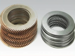
Plate Kit For Twin Disc MG5050 Marine Transmission
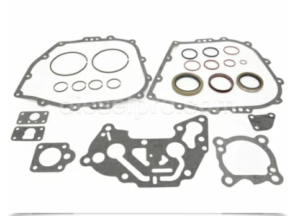
Gasket Kits For Twin Disc MG5050 Marine Transmission
Preparing for Installation
Before installing the Twin Disc MG5050, proper preparation is key to avoiding delays and ensuring a smooth installation. The following steps will help you prepare the workspace, inspect components, and plan for a seamless installation.
1. Inspecting the Marine Gear and Related Components
Before beginning installation, thoroughly inspect the marine gear and related components to identify any shipping damage, missing parts, or defects.
- Check for visible damage (dents, cracks, or leaks) on the transmission housing.
- Ensure all mounting hardware and fasteners are included.
- Inspect the input and output shafts for misalignment or wear.
- Verify compatibility with the engine and drivetrain components.
If you notice any issues, resolve them before proceeding with installation.
2. Preparing the Work Area
A clean, organized workspace is crucial for a successful installation.
- Clear the area of debris and unnecessary tools to prevent accidents.
- Ensure adequate lighting and ventilation in the work area.
- Have a hoist or crane available to lift and position the marine gear properly.
- Ensure all safety precautions are in place before handling heavy components.
3. Reviewing the Installation Manual
Before beginning the installation, carefully read the Twin Disc MG5050 service manual to understand specific manufacturer recommendations, torque specifications, and alignment tolerances.
Tools and Equipment Required
Having the correct tools on hand will make the installation process more efficient and precise. Here is a list of essential tools and equipment required for installing the Twin Disc MG5050 Marine Gear:
Hand Tools
- Wrenches and Socket Set (Metric and SAE sizes)
- Torque Wrench (for precise bolt tightening)
- Screwdrivers (Flathead and Phillips)
- Allen Wrenches (for set screws and small fasteners)
- Pry Bars (for careful adjustments)
Measuring and Alignment Tools
- Dial Indicator (for shaft alignment verification)
- Feeler Gauges (for checking clearance tolerances)
- Straight Edge (to check for level mounting surfaces)
- Plumb Bob or Laser Level (for precise alignment)
Lifting and Handling Equipment
- Engine Hoist or Crane (to position the transmission)
- Lifting Straps or Chains (to secure the marine gear during lifting)
- Jack Stands or Blocks (to support the transmission during installation)
Lubrication and Fluids
- Marine Transmission Oil (as recommended by Twin Disc)
- Anti-Seize Compound (for bolt lubrication)
- Thread Locker (Loctite) (to prevent bolts from loosening)
Safety Equipment
- Safety Gloves and Glasses
- Steel-Toe Boots
- Protective Work Clothing
- Fire Extinguisher (for emergency preparedness)
Step-by-Step Installation Guide
Once preparations are complete, you can begin installing the Twin Disc MG5050 Marine Gear following these steps.
Step 1: Positioning the Transmission
- Use a hoist or crane to carefully position the marine gear near the installation point.
- Align the transmission with the engine flywheel housing before lowering it into position.
- Ensure clearance for mounting bolts and access points.
Step 2: Mounting the Transmission
- Align the transmission housing with the engine mounting points.
- Secure the mounting bolts loosely at first to allow for fine-tuning adjustments.
- Once the transmission is properly aligned, tighten bolts to the recommended torque values.
- Apply Loctite or anti-seize compound on bolts to prevent loosening.
Step 3: Connecting the Input Shaft
- Inspect the splines and couplings on the input shaft before connecting to the engine.
- Apply a light coating of transmission oil to prevent wear.
- Carefully slide the input shaft into place, ensuring proper engagement.
Step 4: Connecting the Output Shaft
- Connect the output shaft to the propeller shaft or drive system.
- Use alignment tools to check for any misalignment that could cause excessive wear.
- Tighten bolts securely and ensure proper coupling engagement.
Step 5: Installing Hydraulic and Electrical Connections
- Connect hydraulic lines for shifting control.
- Ensure that all electrical wiring for sensors and controls is correctly installed.
- Check for leaks or loose connections before proceeding.
Step 6: Filling the Transmission with Oil
- Use only Twin Disc-approved transmission oil.
- Fill the transmission to the recommended level.
- Allow the oil to settle and circulate before checking the level again.
- Inspect for any leaks or unusual noises.
Alignment and Mounting Considerations
Proper alignment and mounting are essential for reducing wear, preventing vibration, and ensuring efficient power transmission.
1. Ensuring Proper Alignment
- Use a dial indicator to check alignment between the engine and transmission shafts.
- Alignment tolerances should be within manufacturer specifications to prevent premature wear.
- If adjustments are needed, use shims or spacers to correct alignment.
2. Checking Mounting Surfaces
- Ensure the mounting surfaces are clean, flat, and free of debris.
- Inspect for cracks or irregularities that may cause instability.
- Use properly rated bolts and washers for secure mounting.
3. Verifying Shaft Coupling Engagement
- The input and output shafts should engage fully and smoothly.
- Ensure that couplings are properly torqued to prevent loosening.
- Inspect for excessive play or movement in the shaft connections.
Post-Installation Checks
Once the Twin Disc MG5050 Marine Gear is installed, post-installation checks must be performed before the system is operational.
1. Final Bolt Torque Inspection
- Recheck all bolts and fasteners to ensure they are tightened to manufacturer specifications.
- Pay special attention to mounting bolts, couplings, and hydraulic connections.
2. Fluid Level and Leak Inspection
- Inspect for oil leaks around seals, gaskets, and connections.
- Verify that the transmission oil level is correct.
- If leaks are detected, tighten fittings or replace seals as necessary.
3. Running a Dry Test
- Before engaging the transmission, perform a manual rotation test of the output shaft.
- Ensure that the transmission spins freely without obstruction.
4. Initial Engine Test Run
- Start the engine and observe transmission engagement.
- Check for abnormal noises, vibrations, or warning indicators.
- Shift through forward, neutral, and reverse gears to verify smooth operation.
5. Load Testing and Performance Evaluation
- Conduct a sea trial or dockside test to assess real-world performance.
- Monitor for vibration, overheating, or shifting issues.
- Make final adjustments as needed.
Final Thoughts on Installing the Twin Disc MG5050 Marine Gear
Proper installation of the Twin Disc MG5050 Marine Gear ensures reliable performance and minimizes long-term maintenance costs. By following this step-by-step installation guide, you can achieve accurate alignment, secure mounting, and efficient power transmission.
If you need replacement parts, maintenance kits, or expert advice, visit Diesel Pro Power for premium aftermarket marine transmission solutions.
By adhering to these installation procedures, you can keep your Twin Disc MG5050 operating at peak performance while ensuring long-term durability and reliability in your marine applications.
Parts Catalog for Twin Disc MG5050 Marine Transmissions
Plate Kit For Twin Disc MG5050 Marine Transmission
Gasket Kits For Twin Disc MG5050 Marine Transmission
Videos About Twin Disc Transmissions
6 Reasons Your Twin Disc Transmission Has Low Oil Pressure
7 Reasons Your Twin Disc Transmission Is Overheating
3 Reasons Your Clutch Plates in Your Twin Disc Transmission Are Making Excessive Noise
Bull Gear On A Twin Disc Transmission
Rebuilt Twin Disc Transmissions