

 Free US Calls: 1-888-433-4735
 International: 305-545-5588

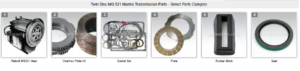
Parts Catalog for Twin Disc MG521 Marine Transmissions
Rebuilt Twin Disc MG521 Marine Transmissions
Plate Kit For Twin Disc MG521 Marine Transmission
Gasket Kits For Twin Disc MG521 Marine Transmission
For reliable propulsion and responsive maneuvering, the control system must be seamlessly integrated with the Twin Disc MG521 marine gear. Whether you’re using a traditional mechanical linkage or the advanced Twin Disc EC300 electronic control system, proper setup is vital for smooth shifting, fast response, and long-term durability. This section explores both control system types in depth, outlining routing, calibration, synchronization, troubleshooting, and bleeding procedures when applicable.
Mechanical Control Linkage vs. EC300 Electronic Controls
The Twin Disc MG521 can be configured for use with either mechanical or electronic controls. Each system has its advantages, limitations, and installation nuances. Your choice may depend on the size of your vessel, operator preference, vessel usage, or upgrade path.
Mechanical Control Linkage
Overview:
- Uses marine-grade push-pull cables to engage forward, neutral, and reverse.
- Relies on manual input and mechanical advantage.
- Suitable for small- to medium-sized vessels and commercial workboats where simplicity and ruggedness are a priority.
Advantages:
- Low cost and easy to maintain.
- No reliance on electronics or power supply.
- Immediate tactile feedback for the operator.
Disadvantages:
- Susceptible to cable stretch over time.
- Greater effort required at helm.
- Cable routing constraints due to friction and bend radius.
Ideal For:
- Fishing boats, tugs, barges, patrol vessels, and vessels without advanced electronics.
EC300 Electronic Controls
Overview:
- Fully electronic shifting using solenoids and hydraulic servo actuators.
- Controlled via helm-mounted levers connected to an electronic processor unit.
- Offers advanced features like throttle sync, warm-up mode, and station transfer.
Advantages:
- Smooth, precise, fingertip control.
- Integrated safety features (e.g., start-in-neutral).
- Built-in diagnostics and LED status indicators.
- Less mechanical wear and no cables to stretch.
Disadvantages:
- Requires dedicated power source and electronic grounding.
- More complex to install and troubleshoot.
- Higher initial cost.
Ideal For:
- Yachts, pilot vessels, modern commercial vessels, dual-station boats.
Cable Routing and Securement
For mechanical control systems, cable routing is one of the most overlooked but critical aspects of setup. Improper routing can cause shift delay, increased resistance, or even premature cable failure. Follow these best practices to ensure reliable control response.
Choosing the Right Cables
- Use Morse 33C Supreme or equivalent premium marine-grade cables.
- Stainless steel core with HDPE jacket for corrosion resistance.
- Match cable length to routing path with no excess slack.
- Lengths over 30 feet should use low-friction or hybrid cables to prevent binding.
Routing Guidelines
- Avoid sharp bends; minimum bend radius is 8 inches.
- Do not allow cables to sag into bilge water.
- Keep cable runs as straight and short as possible.
- Secure every 18–24 inches with cushioned cable clamps.
- Avoid routing near exhaust manifolds or high-heat zones.
- Label each end clearly (e.g., “Transmission FWD”).
Bulkhead and Deck Penetrations
- Use bulkhead cable seals to prevent water ingress.
- Allow drip loops where cables exit above deck.
- Use anti-chafe sleeves in high-friction areas.
Post-Installation Check
- Test full range of motion with control lever disconnected.
- Verify no binding, resistance, or stretching.
- Ensure all anchor points are secure and clamp screws are tight.
Calibrating Control Responses
Whether you’re using mechanical or EC300 controls, calibration is essential to ensure that the control system sends the correct signals and achieves full engagement.
Mechanical Cable Calibration
- Place Control in Neutral:
- Both the control lever and the transmission shift arm should rest in neutral detents.
- Both the control lever and the transmission shift arm should rest in neutral detents.
- Adjust Cable Throw:
- Transmission requires approx. 2.5 to 3.5 inches of cable throw in each direction.
- Adjust the clevis or pivot points to ensure full F-N-R movement.
- Test Full Engagement:
- Shift from neutral to forward and reverse.
- Confirm positive engagement and return to neutral.
- Engine should not stall or struggle during engagement.
- Fine-Tune Lever Tension:
- Add drag washers if needed to improve lever feel.
- Add drag washers if needed to improve lever feel.
EC300 Calibration
- System Initialization:
- After installation, the EC300 will require initial calibration.
- Enter calibration mode via keypad or software interface.
- Shift Position Teach Mode:
- Set transmission to forward and hold for 10 seconds.
- Repeat for neutral and reverse.
- Confirm each position on screen or with LED confirmation.
- Response Time Tuning:
- Adjust actuation delay, if necessary, for smoother shift transitions.
- Ensure clutches fully engage before throttle increase.
- Station Transfer Settings:
- On dual-helm systems, configure which station has priority.
- Add audible or LED feedback for successful transfer.
Synchronization With Throttle Systems
Control integration is not complete without proper throttle sync. Both mechanical and electronic systems require throttle and shift coordination for safe and smooth operation, especially in dual-engine vessels.
Mechanical Systems
- Install a dual-function control lever that integrates shift and throttle.
- Use two cables per station (one for throttle, one for shift).
- Stagger shift timing slightly to avoid clashing with throttle advance.
- Use return springs on throttle cable if engine does not have them.
- Verify idle stop positions on both ends.
EC300 Synchronization
- EC300 offers automatic engine throttle synchronization.
- Ensures both engines maintain the same RPM during cruise.
- Prevents one engine from overloading and improves fuel efficiency.
Setup Process:
- Enable sync mode in system settings.
- Both throttles must be advanced simultaneously to activate.
- Master throttle takes control; slave engine follows.
- System disengages if lever positions diverge significantly.
Warm-Up Mode:
- Allows engine RPM control without engaging gear.
- Ideal for engine prep before departure.
Neutral Interlock:
- Prevents starting the engine if control is not in neutral.
- Enhances safety during startup and engine servicing.
Troubleshooting Control Signal Loss
If the transmission fails to respond to control input, identifying whether it’s a mechanical issue or electronic failure is key. Here’s how to troubleshoot control signal issues:
Mechanical System Failure
Symptoms:
- No shift movement at the gear.
- Cable feels loose or overly stiff.
- Inconsistent engagement or incomplete travel.
Possible Causes & Fixes:
- Cable Stretched or Broken:
- Replace cable and re-route if needed.
- Replace cable and re-route if needed.
- Binding in Cable Sheath:
- Replace if movement feels gritty or inconsistent.
- Replace if movement feels gritty or inconsistent.
- Lever Pivot Corrosion:
- Disassemble, clean, grease, and reinstall.
- Disassemble, clean, grease, and reinstall.
- Incorrect Throw Length:
- Readjust linkage points or pivot arm travel.
- Readjust linkage points or pivot arm travel.
Electronic System Failure
Symptoms:
- EC300 display error or no shift response.
- Gear stuck in neutral or previous position.
- Audible alarm or flashing LEDs.
Possible Causes & Fixes:
- Loss of Power or Ground:
- Check breaker, fuses, and battery connections.
- Verify proper bonding and grounding.
- Controller Failure:
- Reset ECU by cycling power.
- Check for firmware updates or configuration errors.
- Actuator Malfunction:
- Remove actuator cover and check for binding.
- Replace servo if no movement occurs.
- CAN Bus Communication Fault:
- Inspect network cables and connections.
- Replace corrupted components as needed.
- Shift Inhibitor Active:
- Engine in unsafe RPM range or station not confirmed.
- Engine in unsafe RPM range or station not confirmed.
Use Twin Disc diagnostic software or manual override to determine cause.
Control System Bleed Procedures (If Applicable)
If your MG521 is operated by hydraulic servo actuators (common with EC300 systems), bleeding air from the system ensures fast and full clutch engagement.
When Bleeding Is Needed
- After installing new control hoses or actuators.
- Following a fluid change or air introduction from a leak.
- If shift engagement is delayed or inconsistent.
Tools Needed
- Wrenches or line spanners
- Clear tubing and catch bottle
- DOT-approved hydraulic fluid or transmission oil
- Assistant to operate control lever
Bleeding Procedure
- Engine Off – Manual Bleed:
- Locate bleed screw on actuator or slave cylinder.
- Attach clear tubing and submerge in oil bottle.
- Loosen screw and move control lever to full throw in both directions.
- Air bubbles should appear; continue until clear fluid flows.
- Tighten bleed screw and remove tubing.
- Engine On – Dynamic Bleed:
- Start engine and place control in neutral.
- Engage forward and reverse under light load.
- Listen for hesitation; repeat manual bleed if needed.
- Final Checks:
- Recheck fluid reservoir levels.
- Wipe all fittings and observe for leaks.
- Test all stations for consistent shift engagement.
Note: Never operate the vessel under load if air is suspected in the system.
Final Integration Checklist
Before putting your MG521 into full service, complete the following:
- ✅ Shift engages F-N-R from helm and remote stations.
- ✅ Cables or actuators fully extend and retract.
- ✅ No binding, kinks, or sharp bends in cable runs.
- ✅ All connectors tight and free of corrosion.
- ✅ EC300 screen shows no fault codes.
- ✅ Engines and gears throttle up in sync.
- ✅ Emergency neutral override (if equipped) functions correctly.
- ✅ System logs updated with installation details and calibration data.
Conclusion: Precision Control for Long-Term Reliability
The Twin Disc MG521 is only as effective as the control system behind it. Whether you prefer the simplicity of a mechanical setup or the convenience of the EC300’s digital precision, careful integration ensures responsive shifting, operator safety, and drivetrain longevity.
At Diesel Pro Power, we carry everything you need for a complete integration:
- Shift cables and hardware
- EC300 electronic control kits
- Servo actuators and hydraulic lines
- Cable clamps, bulkhead seals, and routing accessories
- Troubleshooting assistance and system diagrams
Rebuilt Twin Disc MG521 Marine Transmissions
Plate Kit For Twin Disc MG521 Marine Transmission
Gasket Kits For Twin Disc MG521 Marine Transmission
Videos About Twin Disc Transmissions
6 Reasons Your Twin Disc Transmission Has Low Oil Pressure
7 Reasons Your Twin Disc Transmission Is Overheating
3 Reasons Your Clutch Plates in Your Twin Disc Transmission Are Making Excessive Noise
Bull Gear On A Twin Disc Transmission
Rebuilt Twin Disc Transmissions