

 Free US Calls: 1-888-433-4735
 International: 305-545-5588

The crankshaft of the Detroit Diesel 53 Series engines is a critical component that transforms linear piston motion into rotational energy to power the engine’s output. Proper handling, inspection, and reinstallation of the crankshaft are essential for ensuring the reliability and efficiency of the engine. This guide will provide comprehensive instructions for removing, inspecting, and installing the crankshaft, along with detailed procedures for measuring end play and grinding worn journals.
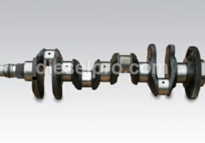
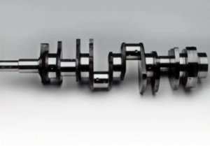
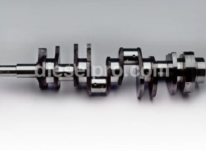
Crankshaft & Related Components for Detroit Diesel 353 Non–Turbo Marine & industrial Engines
Crankshaft & Related Components for Detroit Diesel 353 Turbo Marine & Industrial Engine
Crankshaft & Related Components for Detroit Diesel 453 Non – Turbo Marine & industrial Engines
Crankshaft & Related Components for Detroit Diesel 453 Turbo Marine & industrial Engine
Crankshaft & Related Components for Detroit Diesel 6V53 Non – Turbo Marine & industrial Engines
Crankshaft & Related Components for Detroit Diesel 6V53 Turbo Marine & industrial Engine
Crankshaft & Related Components for Detroit Diesel 8V53 Non – Turbo Marine & industrial Engines
Crankshaft & Related Components for Detroit Diesel 8V53 Turbo Marine & industrial Engine
Guidelines for Crankshaft Removal
Preparation:
- Engine Cleaning:
- Thoroughly clean the exterior of the engine to remove oil, dirt, and debris. This minimizes the risk of contaminating internal components during disassembly.
- Thoroughly clean the exterior of the engine to remove oil, dirt, and debris. This minimizes the risk of contaminating internal components during disassembly.
- Drain Fluids:
- Drain the engine crankcase, cooling system, and any attached accessories, such as a transmission, to facilitate safe removal.
- Drain the engine crankcase, cooling system, and any attached accessories, such as a transmission, to facilitate safe removal.
- Safety Measures:
- Disconnect the battery to avoid accidental engine starts during the process.
- Disconnect the battery to avoid accidental engine starts during the process.
Removal Steps:
- Remove Accessories:
- Disconnect and remove any attached accessories, such as the alternator, air compressor, and power take-off (PTO) devices. This ensures full access to the crankshaft assembly.
- Disconnect and remove any attached accessories, such as the alternator, air compressor, and power take-off (PTO) devices. This ensures full access to the crankshaft assembly.
- Disengage the Transmission:
- Detach the transmission or driven mechanism connected to the flywheel.
- Detach the transmission or driven mechanism connected to the flywheel.
- Mount the Engine:
- Securely mount the engine to an overhaul stand for stability. Use lifting brackets and a hoist to ensure safety during handling.
- Securely mount the engine to an overhaul stand for stability. Use lifting brackets and a hoist to ensure safety during handling.
- Remove the Oil Pan:
- Detach the oil pan to expose the lower components of the engine, including the crankshaft.
- Detach the oil pan to expose the lower components of the engine, including the crankshaft.
- Remove the Flywheel:
- Use caution when removing the flywheel, as it is heavy. Leave at least one bolt or guide pin in place until a lifting tool is attached to prevent accidental falls.
- Use caution when removing the flywheel, as it is heavy. Leave at least one bolt or guide pin in place until a lifting tool is attached to prevent accidental falls.
- Disassemble Connected Components:
- Remove the connecting rod caps, main bearing caps, and thrust washers. Note the order and position of these components for accurate reassembly.
- Remove the connecting rod caps, main bearing caps, and thrust washers. Note the order and position of these components for accurate reassembly.
- Extract the Crankshaft:
- Lift the crankshaft carefully using a hoist to prevent damage to the journals or surrounding components.
- Lift the crankshaft carefully using a hoist to prevent damage to the journals or surrounding components.
Inspection of the Crankshaft
Inspection is critical to identify wear, damage, or potential failures in the crankshaft. This step ensures the component’s suitability for reuse or determines the need for repair or replacement.
Key Areas for Inspection:
- Visual Inspection:
- Look for cracks, scoring, discoloration, or signs of overheating. These defects indicate stress or damage that may render the crankshaft unfit for service.
- Look for cracks, scoring, discoloration, or signs of overheating. These defects indicate stress or damage that may render the crankshaft unfit for service.
- Dimensional Checks:
- Measure the diameter of the main and connecting rod journals using a micrometer. Ensure all measurements fall within the manufacturer’s specifications.
- Check for taper and out-of-round conditions. Acceptable tolerances should not exceed 0.003 inches for either condition.
- Fillet Radii:
- Inspect the journal fillets for sharp edges, as these can concentrate stress and lead to fatigue failures. Ensure smooth transitions and proper radii per specifications: 0.130–0.160 inches for inline engines and 0.100–0.130 inches for V-type engines.
- Inspect the journal fillets for sharp edges, as these can concentrate stress and lead to fatigue failures. Ensure smooth transitions and proper radii per specifications: 0.130–0.160 inches for inline engines and 0.100–0.130 inches for V-type engines.
- Surface Finish:
- Verify that the journal surfaces have a smooth finish (8–12 RMS). Rough surfaces can accelerate bearing wear and reduce lubrication efficiency.
- Verify that the journal surfaces have a smooth finish (8–12 RMS). Rough surfaces can accelerate bearing wear and reduce lubrication efficiency.
- Crack Detection:
- Use non-destructive testing (NDT) methods like magnetic particle inspection or dye penetrant testing to detect cracks in critical stress zones, including the journal fillets and keyways.
- Use non-destructive testing (NDT) methods like magnetic particle inspection or dye penetrant testing to detect cracks in critical stress zones, including the journal fillets and keyways.
Cleaning and Plug Removal:
- Remove all oil plugs and clean the internal oil passages with a stiff wire brush. Blockages can lead to insufficient lubrication and catastrophic engine failure.
- Reinstall plugs after cleaning, using thread sealant to prevent leaks.
Runout Testing:
- Support the crankshaft on V-blocks and use a dial indicator to measure journal runout. Maximum allowable runout is:
- Inline engines: 0.002 inches.
- V-type engines: 0.002 inches for journals adjacent to the support points and 0.004 inches for mid-span journals.
Crankshaft Installation Guidelines
Proper reinstallation of the crankshaft is crucial to ensure the engine’s smooth operation and longevity.
Installation Steps:
- Pre-installation Checks:
- Clean all mating surfaces, oil galleries, and journals.
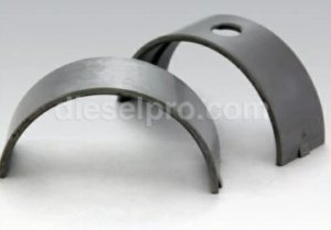
- Inspect main and connecting rod bearings for wear or damage. Always use new bearings when installing a new or reground crankshaft.
- Lubrication:
- Apply clean engine oil to the bearing surfaces and crankshaft journals to reduce friction during initial start-up.
- Apply clean engine oil to the bearing surfaces and crankshaft journals to reduce friction during initial start-up.
- Install the Crankshaft:
- Position the crankshaft in the engine block carefully to avoid damaging the journals or bearings.
- Position the crankshaft in the engine block carefully to avoid damaging the journals or bearings.
- Install Bearings and Caps:
- Place the main bearing caps in their original positions and tighten bolts to the specified torque in sequence to ensure even clamping. Torque values vary based on engine model and should be verified in the service manual.
- Place the main bearing caps in their original positions and tighten bolts to the specified torque in sequence to ensure even clamping. Torque values vary based on engine model and should be verified in the service manual.
- Install Thrust Washers:
- Insert the thrust washers at the rear main bearing to control end play. Ensure the grooved side faces the crankshaft thrust surface.
- Insert the thrust washers at the rear main bearing to control end play. Ensure the grooved side faces the crankshaft thrust surface.
- Verify Alignment:
- Rotate the crankshaft by hand to ensure smooth operation without binding or resistance.
- Rotate the crankshaft by hand to ensure smooth operation without binding or resistance.
Measuring End Play
End play measurement ensures that the crankshaft can move axially within acceptable limits, preventing undue stress on components.
Procedure:
- Mount a Dial Indicator:
- Secure a dial indicator to the engine block with the plunger contacting the crankshaft’s thrust face.
- Secure a dial indicator to the engine block with the plunger contacting the crankshaft’s thrust face.
- Measure Axial Movement:
- Use a pry bar to push the crankshaft forward, zeroing the dial indicator. Reverse the direction and record the total axial movement.
- Use a pry bar to push the crankshaft forward, zeroing the dial indicator. Reverse the direction and record the total axial movement.
- Acceptable Tolerances:
- End play should fall within 0.004 to 0.016 inches for new components and should not exceed 0.018 inches for used components.
- End play should fall within 0.004 to 0.016 inches for new components and should not exceed 0.018 inches for used components.
Addressing Excessive End Play:
- Excessive end play may indicate worn thrust washers or crankshaft thrust surfaces. Replace worn parts and verify clearances before reassembly.
Grinding Specifications for Worn Journals
When journals exhibit wear, scoring, or out-of-round conditions, grinding may restore them to serviceable condition.
Grinding Guidelines:
- Determine Regrind Size:
- Compare journal measurements with standard dimensions:
- Inline engines:
- Standard main journal: 3.000 inches.
- Standard rod journal: 2.500 inches.
- V-type engines:
- Standard main journal: 3.500 inches.
- Standard rod journal: 2.750 inches.
- Inline engines:
- Regrind to the next undersize bearing specification (0.010, 0.020, or 0.030 inches).
- Compare journal measurements with standard dimensions:
- Grinding Process:
- Use a crankshaft grinder with proper cooling to prevent localized heating, which can induce cracks.
- Maintain the specified fillet radii and ensure a smooth transition between surfaces.
- Achieve an 8–12 RMS finish to facilitate proper lubrication.
- Polishing:
- After grinding, polish the journals to remove fine scratches and ensure a smooth bearing surface.
- After grinding, polish the journals to remove fine scratches and ensure a smooth bearing surface.
- Post-Grinding Inspection:
- Conduct magnetic particle inspection to confirm that no cracks have formed during the grinding process.
- Conduct magnetic particle inspection to confirm that no cracks have formed during the grinding process.
Journal Dimensions and Clearance:
- Ensure finished journal dimensions and bearing clearances meet specifications:
- Main bearing clearance:
- Inline and V-type engines: 0.0020–0.0040 inches.
- Inline and V-type engines: 0.0020–0.0040 inches.
- Connecting rod bearing clearance:
- Inline engines: 0.0020–0.0045 inches.
- V-type engines: 0.0020–0.0041 inches.
- Main bearing clearance:
Key Takeaways
- Proper Handling:
- Crankshaft removal and installation require careful handling to avoid damage.
- Crankshaft removal and installation require careful handling to avoid damage.
- Thorough Inspection:
- Perform visual, dimensional, and NDT inspections to identify wear, cracks, or defects.
- Perform visual, dimensional, and NDT inspections to identify wear, cracks, or defects.
- End Play:
- Measure and adjust crankshaft end play within tolerances to prevent axial movement issues.
- Measure and adjust crankshaft end play within tolerances to prevent axial movement issues.
- Grinding and Repair:
- Follow precise grinding specifications to restore worn journals while maintaining factory tolerances.
By following these detailed procedures, you can ensure the proper functioning and longevity of the Detroit Diesel 53 Series crankshaft, safeguarding engine performance and reducing the likelihood of premature failures.
Crankshaft & Related Components for Detroit Diesel 353 Non–Turbo Marine & industrial Engines
Crankshaft & Related Components for Detroit Diesel 353 Turbo Marine & Industrial Engine
Crankshaft & Related Components for Detroit Diesel 453 Non – Turbo Marine & industrial Engines
Crankshaft & Related Components for Detroit Diesel 453 Turbo Marine & industrial Engine
Crankshaft & Related Components for Detroit Diesel 6V53 Non – Turbo Marine & industrial Engines
Crankshaft & Related Components for Detroit Diesel 6V53 Turbo Marine & industrial Engine
Crankshaft & Related Components for Detroit Diesel 8V53 Non – Turbo Marine & industrial Engines
Crankshaft & Related Components for Detroit Diesel 8V53 Turbo Marine & industrial Engine