

 Free US Calls: 1-888-433-4735
 International: 305-545-5588

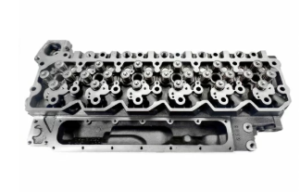
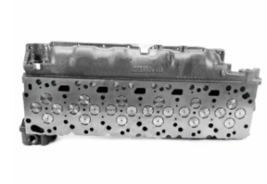
The cylinder head and valve train are critical components in the operation of Cummins ISB and QSB engines. The cylinder head houses key parts like the intake and exhaust valves, valve springs, rocker arms, and fuel injectors. Together, these components manage the air-fuel mixture entering the combustion chamber and the exhaust gases exiting after combustion. Proper maintenance, especially regular valve clearance adjustments, is essential to ensure the engine operates efficiently, reliably, and safely. This comprehensive guide focuses on recognizing the signs that your cylinder head needs attention and the correct procedure for adjusting valve clearances.
Parts Catalog Main Page for Cummins ISB Marine Engine
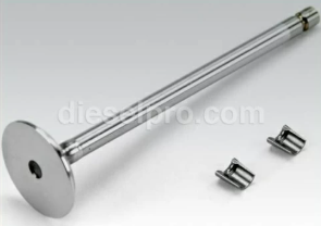
Cylinder Head & Related Components such as Valves & Springs for Cummins ISB 4.5 Engine
Cylinder Head &Related Components such as Valves & Springs for Cummins ISB 5.9 Engine
Cylinder Head & Related Components such as Valves & Springs for Cummins ISB 6.7 Engine
Parts Catalog Main page for Cummins QSB Marine Engine
Cylinder Head & Related Components such as Valves & Springs for Cummins QSB 4.5 Engine
Cylinder Head & Related Components such as Valves & Springs for Cummins QSB 5.9 Engine
Cylinder Head & Related Components such as Valves & Springs for Cummins QSB 6.7 Engine
Cylinder Head & Related Components such as Valves & Springs for Cummins QSB 7.0 Engine
1. Signs That Your Cylinder Head Needs Attention
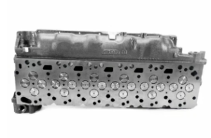
The cylinder head is a vital part of the engine’s structure, sealing the top of the combustion chamber and enabling proper compression for efficient combustion. Over time, the cylinder head can experience wear and damage due to extreme temperatures, pressure fluctuations, and mechanical stress.
A. Common Symptoms of Cylinder Head Problems
Recognizing early warning signs of cylinder head issues can help prevent costly engine repairs and extended downtime.
1. Loss of Engine Power
- Symptoms: The engine feels sluggish, struggles to accelerate, or cannot maintain power under load.
- Possible Causes: A warped or cracked cylinder head reduces compression, leading to inefficient combustion and reduced engine output.
2. Overheating
- Symptoms: The engine frequently overheats despite a properly functioning cooling system.
- Possible Causes: A cracked cylinder head can cause coolant to leak into the combustion chamber, reducing the cooling system’s effectiveness.
3. White Smoke from the Exhaust
- Symptoms: Persistent white smoke, often with a sweet smell, indicates coolant burning in the combustion chamber.
- Possible Causes: A blown head gasket or cracked cylinder head allows coolant to enter the combustion chamber.
4. Oil Contamination (Milky Oil)
- Symptoms: A milky or frothy substance on the dipstick or under the oil filler cap.
- Possible Causes: Coolant mixing with engine oil due to a failed head gasket or cylinder head crack.
5. Misfiring or Rough Idling
- Symptoms: The engine runs unevenly, shakes excessively, or struggles to maintain a steady idle.
- Possible Causes: Poor valve seating, loss of compression, or coolant intrusion into the cylinders.
6. External Coolant Leaks
- Symptoms: Visible coolant leaks around the cylinder head or engine block.
- Possible Causes: A damaged head gasket or cylinder head may cause coolant to escape externally.
7. Unusual Engine Noises
- Symptoms: Knocking, tapping, or ticking sounds from the top of the engine.
- Possible Causes: Improper valve clearances, valve seat damage, or rocker arm wear.
B. Causes of Cylinder Head Damage
Understanding the root causes of cylinder head damage helps in both prevention and timely intervention.
- Overheating: The most common cause of cylinder head warping or cracking. Regular coolant system maintenance can prevent this.
- Poor Maintenance: Neglecting oil changes, valve adjustments, or coolant flushes can accelerate wear and lead to damage.
- Detonation (Knocking): Abnormal combustion can create extreme pressure spikes, damaging the cylinder head and valves.
- Manufacturing Defects: Rare, but casting flaws can weaken the cylinder head structure over time.
2. Adjusting Valve Clearances Correctly
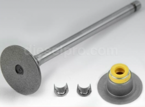
The valve clearance (also known as valve lash) is the gap between the rocker arm and the valve stem or camshaft. This clearance ensures the valves open and close at the correct times, allowing optimal air-fuel mixture intake and exhaust gas expulsion. Incorrect valve clearances can lead to poor engine performance, increased wear, and even engine damage.
A. Why Valve Clearance Adjustment Is Important

Proper valve clearance is essential for several reasons:
- Maintains Engine Efficiency: Correct clearance ensures valves open and close fully, optimizing airflow and combustion.
- Prevents Engine Damage: Too tight clearance can cause valves to overheat and fail; too loose clearance leads to noisy operation and reduced performance.
- Extends Component Life: Regular adjustments reduce wear on the camshaft, rocker arms, and valves.
B. Symptoms of Incorrect Valve Clearance
1. Ticking or Tapping Noise
- Cause: Excessive clearance causes noisy valve operation, commonly referred to as valve ticking.
2. Poor Engine Performance
- Cause: Tight clearances can prevent valves from closing fully, leading to compression loss and reduced power.
3. Hard Starting or No Start
- Cause: Improper valve timing can affect the air-fuel mixture, making the engine difficult to start.
4. Misfires and Rough Idling
- Cause: Uneven valve operation causes inconsistent combustion.
5. Increased Fuel Consumption
- Cause: Inefficient combustion due to poor valve timing leads to higher fuel usage.
C. Tools Needed for Valve Adjustment
- Feeler gauge set (measured in thousandths of an inch or millimeters)
- Torque wrench
- Screwdriver
- Socket set and wrenches
- Engine service manual (for specific clearance specs)
- Marker or chalk (to mark the crankshaft pulley)
D. Step-by-Step Valve Clearance Adjustment
Step 1: Preparation
- Ensure the Engine Is Cool:
- Valve adjustments should be performed on a cold engine to ensure accurate measurements.
- Valve adjustments should be performed on a cold engine to ensure accurate measurements.
- Disconnect the Battery:
- Prevents accidental engine cranking during the procedure.
- Prevents accidental engine cranking during the procedure.
- Remove Engine Covers:
- Take off any components obstructing access to the valve cover, such as air intake ducts or wiring harnesses.
- Take off any components obstructing access to the valve cover, such as air intake ducts or wiring harnesses.
- Remove the Valve Cover:
- Carefully unbolt and remove the valve cover to expose the rocker arms and valve train.
- Carefully unbolt and remove the valve cover to expose the rocker arms and valve train.
Step 2: Position the Engine at Top Dead Center (TDC)
- Locate Cylinder 1:
- Refer to the engine’s firing order to identify cylinder 1.
- Refer to the engine’s firing order to identify cylinder 1.
- Rotate the Crankshaft:
- Use a breaker bar and socket on the crankshaft pulley bolt to turn the engine clockwise.
- Align the timing mark on the crankshaft pulley with the TDC mark on the timing cover.
- Confirm TDC on Compression Stroke:
- Ensure both intake and exhaust valves for cylinder 1 are closed (rocker arms slightly loose).
- If not, rotate the crankshaft 360° and check again.
Step 3: Measure Valve Clearance
- Insert Feeler Gauge:
- Place the appropriate feeler gauge between the rocker arm and the valve stem tip.
- Place the appropriate feeler gauge between the rocker arm and the valve stem tip.
- Check the Clearance:
- The feeler gauge should slide with slight resistance.
- Compare the measurement with the specifications from the Cummins service manual.
Step 4: Adjust the Valve Clearance
- Loosen the Lock Nut:
- Use a wrench to hold the adjuster screw while loosening the lock nut.
- Use a wrench to hold the adjuster screw while loosening the lock nut.
- Adjust the Clearance:
- Turn the adjuster screw with a screwdriver to increase or decrease the gap.
- Reinsert the feeler gauge to check for proper clearance.
- Tighten the Lock Nut:
- Once the clearance is correct, hold the adjustment screw in place and tighten the lock nut to the specified torque.
- Once the clearance is correct, hold the adjustment screw in place and tighten the lock nut to the specified torque.
Step 5: Repeat for All Valves
- Follow the Firing Order:
- Rotate the crankshaft 360° to position the next cylinder at TDC on the compression stroke.
- Repeat the measurement and adjustment process for each valve.
- Double-Check Adjustments:
- After completing all adjustments, go back and verify the clearances to ensure accuracy.
- After completing all adjustments, go back and verify the clearances to ensure accuracy.
Step 6: Reassembly
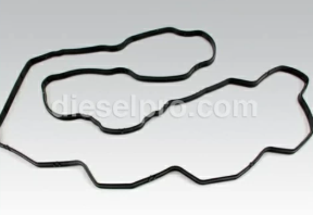
- Clean the Valve Cover Gasket Surface:
- Remove old gasket material and apply a new gasket if necessary.
- Remove old gasket material and apply a new gasket if necessary.
- Reinstall the Valve Cover:
- Torque the cover bolts evenly to prevent leaks.
- Torque the cover bolts evenly to prevent leaks.
- Reconnect Battery and Components:
- Reattach any parts removed for access.
- Reattach any parts removed for access.
- Start the Engine:
- Listen for unusual noises and ensure smooth idling.
- Check for oil leaks around the valve cover.
E. Valve Clearance Specifications
Valve clearance specifications vary depending on the engine model and application. Always refer to the Cummins service manual for precise measurements. For example:
- Intake Valve Clearance: 0.010 – 0.012 inches (0.25 – 0.30 mm)
- Exhaust Valve Clearance: 0.020 – 0.024 inches (0.50 – 0.60 mm)
F. Common Mistakes to Avoid
- Not Setting TDC Correctly:
- Failing to position the piston at TDC on the compression stroke leads to inaccurate adjustments.
- Failing to position the piston at TDC on the compression stroke leads to inaccurate adjustments.
- Over-Tightening the Lock Nut:
- Can strip threads or affect valve clearance settings.
- Can strip threads or affect valve clearance settings.
- Ignoring Valve Wear:
- Worn valve stems or rocker arms can give false clearance readings.
- Worn valve stems or rocker arms can give false clearance readings.
- Skipping Double-Checks:
- Always recheck clearances after tightening the lock nuts.
- Always recheck clearances after tightening the lock nuts.
G. When to Adjust Valve Clearances
- After Engine Rebuilds: Any time the cylinder head is removed or major repairs are done.
- Routine Maintenance: Typically every 150,000 to 200,000 miles or as specified in the maintenance schedule.
- If Symptoms Appear: Ticking noises, loss of power, or rough idling.
H. Benefits of Regular Valve Adjustments
- Improved Engine Performance: Proper valve timing ensures efficient combustion.
- Extended Engine Life: Reduces stress on the valve train and prevents premature wear.
- Fuel Efficiency: Optimal combustion reduces fuel consumption.
- Lower Emissions: Correct valve operation minimizes unburned fuel in exhaust gases.
Conclusion
Proper maintenance of the cylinder head and valve train is essential for the reliable operation of Cummins ISB and QSB engines. Recognizing signs of cylinder head problems, such as overheating, white smoke, or loss of power, allows for early intervention. Additionally, performing regular valve clearance adjustments ensures that the engine runs efficiently, reduces wear, and extends its lifespan.
By following the step-by-step guide provided, you can confidently diagnose and adjust valve clearances, ensuring optimal performance and preventing costly repairs. Always refer to the Cummins service manual for specific procedures, torque specifications, and valve clearance measurements tailored to your engine model.
Parts Catalog Main Page for Cummins ISB Marine Engine
Cylinder Head & Related Components such as Valves & Springs for Cummins ISB 4.5 Engine
Cylinder Head &Related Components such as Valves & Springs for Cummins ISB 5.9 Engine
Cylinder Head & Related Components such as Valves & Springs for Cummins ISB 6.7 Engine
Parts Catalog Main page for Cummins QSB Marine Engine
Cylinder Head & Related Components such as Valves & Springs for Cummins QSB 4.5 Engine
Cylinder Head & Related Components such as Valves & Springs for Cummins QSB 5.9 Engine
Cylinder Head & Related Components such as Valves & Springs for Cummins QSB 6.7 Engine
Cylinder Head & Related Components such as Valves & Springs for Cummins QSB 7.0 Engine