

 Free US Calls: 1-888-433-4735
 International: 305-545-5588

The cylinder head of Detroit Diesel 53 Series engines is a critical component that ensures the efficient operation of the engine by housing the valves, injectors, and associated operating mechanisms. Proper maintenance and handling are crucial to maximize engine performance and longevity.
Cylinder Head & Related Components for Detroit Diesel 353 Non – Turbo Marine & industrial Engines
Cylinder Head & Related Components for Detroit Diesel 353 Turbo Marine & industrial Engine
Cylinder Head & Related Components for Detroit Diesel 453 Non – Turbo Marine & industrial Engines
Cylinder Head & Related Components for Detroit Diesel 453 Turbo Marine & industrial Engine
Cylinder Head & Related Components for Detroit Diesel 6V53 Non – Turbo Marine & industrial Engines
Cylinder Head & Related Components for Detroit Diesel 6V53 Turbo Marine & industrial Engine
Cylinder Head & Related Components for Detroit Diesel 8V53 Non – Turbo Marine & industrial Engines
Cylinder Head & Related Components for Detroit Diesel 8V53 Turbo Marine & industrial Engine
Exhaust Valve and Injector Tube Guide For Detroit Diesel 53 Series Engines (3-53, 4-53, 6V53, 8V53)
Key Features of Exhaust Valves
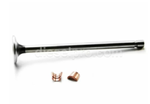
Heat-Treated Valve Heads
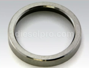
The exhaust valve heads in Detroit Diesel 53 Series engines are heat-treated for enhanced durability and resistance to wear. They are ground to a 30-degree seating angle, ensuring a tight seal against the valve seat insert. This precise fit prevents compression loss and enhances engine efficiency.
Hardened Valve Stems
Exhaust valve stems are hardened at the contact points where they meet the rocker arms or valve bridges. This added hardness prevents premature wear and ensures long-term reliability.
Valve Springs and Locks
Each exhaust valve is paired with a high-strength spring, retained by a valve spring cap and two-piece tapered valve locks. This setup ensures proper valve movement and prevents excessive vibration that could lead to failure.
Maintenance Guidelines
Inspection of Valve Seats
- Check valve seats regularly for pitting, deposits, or uneven wear that may compromise sealing.
- Ensure valve seats are smooth and concentric using a valve seat grinder and dial gauge for precise alignment.
- Valve seat inserts are ground to a 31-degree angle to match the 30-degree valve face, providing an airtight seal.
Valve Clearance Adjustment

Cold Engine Adjustment
- Remove the valve rocker cover.
- Rotate the crankshaft clockwise until the injector follower is fully depressed for the cylinder being adjusted.
- Loosen the exhaust valve rocker arm push rod locknut.
- Insert a 0.026-inch feeler gauge between the exhaust valve stem and the rocker arm bridge. Adjust the push rod until the gauge slides with slight resistance.
- Secure the locknut and verify clearance: a 0.025-inch gauge should pass freely, while a 0.027-inch gauge should not.
Hot Engine Adjustment
- If adjusting at normal operating temperature, use a 0.023-inch feeler gauge instead.
Addressing Carbon Deposits
- Carbon buildup on valve stems is caused by low engine operating temperatures or poor fuel quality.
- Deposits hinder valve movement, leading to loss of compression.
- Regular cleaning of valve stems and seats prevents sticking and ensures smooth operation.
Avoiding Valve Breakage
- Always use specified valve springs and correct torque values for fasteners.
- Never mix high-lift and low-lift valve springs within the same engine.
- Use a spring tester to verify valve spring loads and replace weak springs.
Tools and Techniques for Valve Maintenance

Valve Spring Removal and Installation
- A spring compressor allows for the removal of exhaust valve springs without disassembling the cylinder head.
- After installation, compress the valve springs and install the two-piece tapered valve locks to secure them.
Checking Valve Opening Pressure
- Use a spring tester to verify that the exhaust valve requires at least 33 lbs (two-valve head) or 25 lbs (four-valve head) to open.
Injector Tube Handling

Design Features of Fuel Injector Tubes
Injector tubes direct fuel into the combustion chamber and prevent coolant contamination.
- Thin-Walled Tubes: They pass through the water jacket, cooling the injectors.
- Sealed Upper and Lower Ends: Prevents leaks and ensures long service life.
Injector Tube Installation and Removal
Removal Process
- Remove the fuel injector.
- Use a specialized service tool to loosen and extract the injector tube.
- If leaking, replace the tube to maintain a proper fuel and coolant seal.
Installation Process
- Clean the injector tube bore to remove any debris.
- Lubricate the seal ring and place it into the cylinder head’s counterbore.
- Insert the new injector tube and use a pressing tool to secure it.
- Flare the lower end of the injector tube to complete the seal.
Reaming the Injector Tube
- The tube must be reamed in three stages:
- Hand ream the injector nut seating area for a snug fit.
- Spot-face the lower end to remove excess material.
- Hand ream the lower seating surface to ensure a tight seal.
- Hand ream the injector nut seating area for a snug fit.
Final Checks and Engine Operation
Valve and Injector Timing
- Ensure fuel injector followers are properly adjusted.
- Use an injector timing gauge for correct dimensioning.
Verifying Valve and Injector Operation
- Conduct a compression test to confirm proper sealing.
- If compression loss is detected, inspect valve seats, injector tubes, and gaskets.
Sealing Techniques for the Cylinder Head – Detroit Diesel 53 Series (3-53, 4-53, 6V53, 8V53)
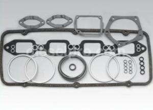
Achieving a robust seal between the cylinder head and engine block is essential for preventing fluid leaks, maintaining compression, and ensuring long-term engine reliability. The Detroit Diesel 53 Series engines use high-quality gaskets, synthetic rubber seals, and a structured bolt torque sequence to ensure durability under extreme conditions.
Key Sealing Components
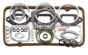
Laminated Metal Compression Gaskets
Detroit Diesel 53 Series engines utilize laminated metal compression gaskets to provide a secure seal between the cylinder head and the engine block. These gaskets are available in two designs:
- One-piece gaskets: Thickness between 0.059–0.063 inches
- Two-piece gaskets: Thickness between 0.070–0.085 inches
Both gasket designs are interchangeable and can be used together in the same engine.
Synthetic Rubber Seal Rings
Synthetic rubber seal rings are used to seal water and oil passages between the cylinder head and block. These rings fit into counterbored holes in the engine block, preventing oil leaks, coolant leaks, and loss of compression.
Fuse Plugs for Overheating Protection
- Heat-sensitive fuse plugs are installed on the exhaust manifold side of the cylinder head.
- If the cylinder head temperature exceeds 291°F (144°C), the insert in the fuse plug melts, preventing catastrophic engine damage.
- If a fuse plug is found melted, the cylinder head must be removed and inspected for warping, cracking, or injector tube failure.
Proper Sealing Procedures
Preparation Before Installation
Before installing the cylinder head, a thorough cleaning and inspection of all mating surfaces is essential.
- Clean the cylinder head and engine block surfaces to remove oil, debris, or old gasket material.
- Inspect cylinder block counterbores for nicks, scratches, or imperfections that could prevent a proper seal.
- Ensure that cylinder liner flange heights are within specification.
Gasket and Seal Installation
Installing Cylinder Head Gaskets
- Place a new compression gasket on top of each cylinder liner.
- Install new water and oil seal rings in the counterbores of the engine block.
- Apply a high-tack adhesive to the seal counterbores to prevent movement during installation.
Important: Never reuse old gaskets or seals, as they degrade over time and may lead to leaks.
Installing the Cylinder Head
To prevent gasket shifting and seal displacement, follow these guidelines:
- Use guide studs in the cylinder block bolt holes to align the cylinder head.
- Attach a lifting tool to position the head accurately.
- Ensure all gaskets and seals are properly seated before fully lowering the cylinder head onto the block.
Cylinder Head Bolt Torqueing Sequence

Step-by-Step Torqueing Procedure
- Apply a small amount of anti-seize compound to the threads of each head bolt to ensure uniform clamping force.
- Install the bolts finger tight, then follow a structured torque sequence.
Torque Specifications for Cylinder Head Bolts
General Torque Sequence
Torque bolts in three stages, using the specified sequence:
- First pass: 50 lb-ft (68 N·m)
- Second pass: 100 lb-ft (136 N·m)
- Final torque: 170-180 lb-ft (231-244 N·m)
- Apply steady pressure for 2–3 seconds per bolt to allow the gaskets to compress properly.
- Repeat the torque sequence to ensure uniform pressure across the cylinder head.
- Use a calibrated torque wrench to maintain accuracy.
Variations for Specific Engine Models
-
3-53 & 4-53 In-line Engines
- The torque procedure remains the same, but it is crucial to ensure proper alignment of the gasket and counterbores before tightening.
- The bolt tightening sequence must begin at the center and work outward in a spiral pattern to prevent warping.
-
6V53 & 8V53 V-Type Engines
- The V-type cylinder heads require the same torque values, but the sequence varies slightly.
- Begin tightening on the cam follower side to take up tension in the push rod springs.
- Check valve bridges before torquing; if misaligned, improper tightening can damage exhaust valves.
Additional Considerations
- Guide studs should be used for accurate head alignment before torquing.
- Do not exceed the torque limit, as over-tightening may cause bolt stretching beyond elastic limits.
- Cylinder head bolt rechecking is necessary after the first heat cycle to account for gasket compression and thermal expansion.
This procedure ensures proper sealing, prevents warping, and extends engine life across all Detroit Diesel 53 Series models.
- First pass: 50 lb-ft (68 N·m)
Comprehensive Guide to Leak Testing for Detroit Diesel 53 Series Engines
Ensuring a leak-free cylinder head is critical for maintaining engine performance, preventing fluid loss, and extending the service life of the Detroit Diesel 53 Series engines. This guide covers comprehensive leak detection methods, including cooling system pressure testing, fuel leak detection with fluorescent dye, and cylinder head reconditioning to address any discovered faults.
Cooling System Pressure Test
After the cylinder head installation, a pressure test should be performed to detect any leaks in the cooling system. A failure to conduct this test may result in undetected leaks that lead to engine overheating, loss of coolant, or head gasket failure.
Testing Procedure
- Apply 40 psi (276 kPa) air pressure to the engine’s water jacket.
- Immerse the cylinder head in a heated water tank at 180-200°F (82-93°C) for approximately 20 minutes.
- Observe the water surface for bubbles, which indicate a leak.
- Check common leak points, including:
- Injector tubes (top and bottom)
- Oil gallery
- Exhaust ports
- Fuel manifolds
- Cylinder head top and bottom surfaces
If Leaks Are Detected
- Retorque the head bolts following the prescribed torque sequence.
- Inspect all gaskets and seals, replacing any that show signs of failure.
- Remove and dry the cylinder head with compressed air after completing the test.
CAUTION: Always wear protective eyewear and never exceed 40 psi (276 kPa) when pressurizing the cooling system to avoid personal injury.
Fuel Leak Detection with Fluorescent Dye
For engines already in service, fuel leaks can be detected using fluorescent dye and a black light (ultraviolet light). This method is particularly useful when dark lubricating oil is present, making traditional leak detection difficult.
Testing Procedure
-
Prepare the test fuel:
- Mix 4 oz of fluorescent dye (J 28431) with 4 gallons of clean diesel fuel.
- Store the fuel in a marked and resealable container to prevent contamination.
-
Isolate the fuel system:
- Disconnect the normal fuel supply and return lines.
- Connect them to the test fuel container.
-
Operate the engine:
- Start and run the engine at maximum no-load speed for approximately 5 minutes to bring it to operating temperature.
- Ensure the test fuel level is maintained throughout the test.
-
Inspect for leaks:
- Remove the rocker covers and shine a black light over the cylinder head assembly.
- Fuel leaks will appear bright yellow under UV light.
-
Correct detected leaks:
- If leaks are found, wipe the area clean, tighten or replace affected components, and retest.
- If leaks are found, wipe the area clean, tighten or replace affected components, and retest.
-
Final Steps:
- Reconnect original fuel lines and restore normal fuel supply.
- Purge the fuel system of air by running the engine.
Note: Some minor fuel leakage may be normal, but excessive leakage should be addressed immediately to prevent lube oil dilution.
Final Checks After Assembly
After completing leak detection tests, additional inspections should be performed to confirm proper sealing and system integrity.
Compression Test
- A compression test verifies that the cylinder head, valves, and gaskets are properly sealed.
- If compression readings are uneven or low, inspect for:
- Leaking injector tubes
- Head gasket failure
- Valve seat damage
Coolant System Integrity Check
-
Check for unexpected coolant loss, which could indicate:
- A failing head gasket
- Cracks in the cylinder head
- Loose injector tubes allowing compression leaks into the cooling system
-
Recheck head bolt torque values after engine heat cycles to account for gasket compression and thermal expansion.
Inspection and Reconditioning Procedures
A comprehensive reconditioning process is essential for restoring the cylinder head to peak operating condition. This involves visual inspections, dimensional checks, resurfacing, and pressure testing.
Steps for Cylinder Head Inspection and Reconditioning

1. Visual and Dimensional Checks
- Inspect the fire deck for warping using a straightedge and feeler gauge.
- Measure critical dimensions, including:
- Valve seat insert protrusion
- Valve-to-cylinder head clearance
- Injector tube fitment
2. Pressure Testing for Cracks
To ensure there are no internal cracks, perform a pressure test on the cylinder head:
- Seal all water jacket ports using steel plates and rubber gaskets.
- Install scrap injectors to properly seat injector tubes.
- Apply air pressure to the water jackets while submerging the head in heated water.
- Check for bubbles, which indicate cracks in the casting.
CAUTION: If any cracks are found, the cylinder head should not be reused. Welding is not recommended for Detroit Diesel 53 Series cylinder heads.
3. Grinding and Resurfacing
- Valve seats should be reground to a 31° angle, ensuring a tight seal with the 30° valve face.
- Resurface the cylinder head to correct warping or imperfections, while maintaining the minimum thicknessspecifications.
4. Final Assembly
- Apply Loctite Pipe Sealant with Teflon to all threaded plugs to prevent leaks.
- Reassemble the cylinder head with cleaned and inspected components, ensuring:
- Proper lubrication during assembly
- Correct torquing of all bolts and fasteners
Conclusion
Leak testing and reconditioning are critical for ensuring long-term performance and reliability in Detroit Diesel 53 Series engines. By following these detailed procedures, engine operators can:
- Prevent costly repairs by detecting leaks early.
- Ensure efficient fuel combustion and cooling with a properly sealed cylinder head.
- Maximize engine lifespan by maintaining optimal operating conditions.
A thorough and methodical approach to testing, inspecting, and reassembling the cylinder head will provide consistent performance and durability in any Detroit Diesel 53 Series engine.
Cylinder Head & Related Components for Detroit Diesel 353 Non – Turbo Marine & industrial Engines
Cylinder Head & Related Components for Detroit Diesel 353 Turbo Marine & industrial Engine
Cylinder Head & Related Components for Detroit Diesel 453 Non – Turbo Marine & industrial Engines
Cylinder Head & Related Components for Detroit Diesel 453 Turbo Marine & industrial Engine
Cylinder Head & Related Components for Detroit Diesel 6V53 Non – Turbo Marine & industrial Engines
Cylinder Head & Related Components for Detroit Diesel 6V53 Turbo Marine & industrial Engine
Cylinder Head & Related Components for Detroit Diesel 8V53 Non – Turbo Marine & industrial Engines
Cylinder Head & Related Components for Detroit Diesel 8V53 Turbo Marine & industrial Engine