

 Free US Calls: 1-888-433-4735
 International: 305-545-5588

Exhaustive Torque Tables for Bolts, Nuts, and Other Fasteners
Proper torque specifications are crucial for maintaining the structural integrity and performance of Detroit Diesel V71 engines. Every fastener has a specific torque requirement based on its function, material, and location within the engine. Over-tightening can lead to material failure or deformation, while under-tightening can result in loosening, leaks, or damage during operation. Below is a comprehensive guide to torque specifications for the most critical fasteners on the V71 engine series.
-
Detroit Diesel V71 Engines (6V71, 8V71, 12V71, 16V71) Cylinder Head Assembly Torque Specifications
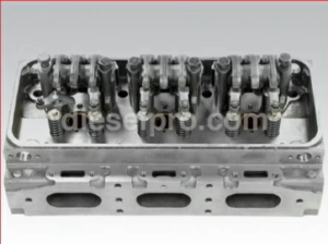
Complete Cylinder Head for Detroit Diesel 6V71 Non- turbo
This comprehensive guide covers the torque specifications for the cylinder head assembly across all V71 engine models, including marine and non-marine applications.
Cylinder Head Assembly Torque Specifications
Component Torque Specification Notes Cylinder Head Bolts 165–175 lb-ft (224–237 N•m) Tighten in sequence, as outlined in the manual. Re-torque after initial engine operation. Rocker Arm Shaft Bolts 35–45 lb-ft (47–61 N•m) Ensure even tightening to prevent shaft distortion. Injector Hold-Down Nuts 40–50 lb-ft (54–68 N•m) Use a calibrated torque wrench for accuracy. Valve Cover Bolts 15–20 lb-ft (20–27 N•m) Avoid over-tightening to prevent gasket damage. Exhaust Manifold Bolts 30–35 lb-ft (41–47 N•m) Tighten evenly to avoid warping the manifold. Intake Manifold Bolts 30–35 lb-ft (41–47 N•m) Use a crisscross pattern to ensure even sealing. Thermostat Housing Bolts 18–22 lb-ft (24–30 N•m) Ensure even torque to prevent leaks. Thermostat Cover Bolts 15–20 lb-ft (20–27 N•m) Tighten evenly to avoid cracking the cover. Injector Tube Retainer Nuts 15–20 lb-ft (20–27 N•m) Prevents movement of injector tubes; avoid over-tightening. Glow Plug (if applicable) 15–20 lb-ft (20–27 N•m) Apply anti-seize compound to prevent seizing. Rocker Arm Adjusting Screw Locknuts 35–40 lb-ft (47–54 N•m) Adjust valve lash before final tightening. Water Outlet Housing Bolts 18–22 lb-ft (24–30 N•m) Tighten evenly to prevent gasket leaks. Coolant Crossover Pipe Bolts 30–35 lb-ft (41–47 N•m) Ensure proper alignment to avoid leaks. Fuel Line Fittings 15–20 lb-ft (20–27 N•m) Use thread sealant where required.
Assembly Best Practices
- Tightening Sequence: Always follow the specified bolt tightening sequence to ensure even clamping of the cylinder head and prevent distortion. Start from the center bolts and move outward in a crisscross pattern.
- Re-Torque Process: Re-torque the cylinder head bolts after the initial engine operation (after warm-up and cool-down) to account for gasket compression and material settling.
- Gasket Preparation: Always install new gaskets and inspect surfaces for flatness and cleanliness to avoid leaks.
- Lubrication: Apply appropriate thread lubricant or sealant as required, especially on bolts exposed to coolant or oil passages.
- Post-Assembly Check: After the engine runs for the first time, check for leaks and retorque if necessary.
Cylinder Head & Related Components for Detroit Diesel V71 Engines
- Tightening Sequence: Always follow the specified bolt tightening sequence to ensure even clamping of the cylinder head and prevent distortion. Start from the center bolts and move outward in a crisscross pattern.
-
Detroit Diesel V71 Engines (6V71, 8V71, 12V71, 16V71) Main Bearing Caps and Connecting Rods Torque Specifications
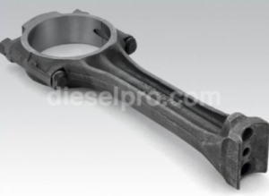
Connecting rod for Detroit Diesel 6V71,8V71,12V71 and 16V71 Engines with 2 piece piston
This comprehensive guide covers all torque specifications for main bearing caps, connecting rods (for both two-piece and one-piece pistons), and related components across all Detroit Diesel V71 engine models.
Main Bearing Caps and Connecting Rods Torque Specifications
Component Torque Specification Notes Main Bearing Cap Bolts 165–175 lb-ft (224–237 N•m) Tighten in two stages to ensure uniform clamping. Connecting Rod Cap Bolts (Two-Piece Pistons) 45–50 lb-ft (61–68 N•m) plus a 90° turn Use the torque-plus-angle method for proper clamping force. Connecting Rod Cap Bolts (One-Piece Pistons) 80–85 lb-ft (108–115 N•m) Ensure bolts are tightened evenly and to final torque. Connecting Rod Nut (if applicable) 35–40 lb-ft (47–54 N•m) Use a calibrated torque wrench for precision. Flywheel Housing Bolts 65–75 lb-ft (88–102 N•m) Check for even distribution across all bolts. Crankshaft Thrust Bearing Bolts 30–35 lb-ft (41–47 N•m) Tighten gradually to avoid distorting the bearing. Rod Side Clearance Check 0.005–0.015 in (0.13–0.38 mm) Ensure clearance is within spec after assembly. Piston Pin Retaining Bolt 35–40 lb-ft (47–54 N•m) Tighten securely to avoid pin movement during operation.
Assembly Best Practices
- Tightening Sequence: Always follow the tightening sequence recommended in the manual for main bearing cap bolts and connecting rod bolts to ensure even clamping.
- Torque-Plus-Angle Method: For two-piece piston connecting rods, first tighten bolts to 45–50 lb-ft, then perform an additional 90° turn for proper clamping force.
- Re-Torque Procedure: After initial engine operation, recheck the torque for main bearing caps and connecting rods to account for settling.
- Lubrication: Apply assembly lubricant to all threads and under bolt heads to achieve accurate torque readings.
- Side Clearance Check: After assembling connecting rods, always check side clearance to ensure it falls within the specified range for optimal operation.
- Surface Cleanliness: Ensure that all mating surfaces, including rod caps and bearing caps, are free from debris, oil, or old gasket material.
- Bolt Replacement: Replace any bolts that show signs of stretching, corrosion, or damage to maintain assembly integrity.
Connecting Rod & Related Components for Detroit Diesel V71 Engines
- Tightening Sequence: Always follow the tightening sequence recommended in the manual for main bearing cap bolts and connecting rod bolts to ensure even clamping.
-
Detroit Diesel V71 Engines (6V71, 8V71, 12V71, 16V71) Lubrication System Torque Specifications

Oil Pump For Detroit Diesel 6V71 & 8V71 Engines (Left Hand)
This guide covers all torque specifications for the lubrication system components across all Detroit Diesel V71 engine models, including both marine and non-marine applications.
Lubrication System Torque Specifications
Component Torque Specification Notes Oil Pump Gear Retaining Bolts 13–17 lb-ft (18–23 N•m) Self-locking bolts are mandatory to prevent loosening. Oil Pump Mounting Bolts (6V71 & 8V71) 15–20 lb-ft (20–27 N•m) Ensure proper alignment and use new gaskets if necessary. Oil Pump Mounting Bolts (12V71 & 16V71) 35–45 lb-ft (47–61 N•m) Tighten evenly to avoid pump misalignment. Oil Pan Bolts 15–20 lb-ft (20–27 N•m) Tighten starting from the center and work outward. Oil Cooler Housing Bolts 30–35 lb-ft (41–47 N•m) Use new gaskets during reassembly to avoid leaks. Oil Cooler Bypass Valve Plug 95–105 lb-ft (129–142 N•m) (1 1/4″-16 thread) 110–130 lb-ft (150–177 N•m) (1 1/2″-6 thread)
Ensure the plug is secure to prevent leaks. Oil Pressure Relief Valve Plug 30–35 lb-ft (41–47 N•m) Replace gaskets if worn to prevent oil leaks. Oil Pressure Regulator Retaining Pin Press flush to 0.010″ below surface Ensure correct positioning for proper valve operation. Oil Filter Adaptor Mounting Bolts 30–35 lb-ft (41–47 N•m) Tighten evenly to avoid oil leaks. Oil Filter Center Stud (Full-Flow Filter) 50–60 lb-ft (68–81 N•m) Use a calibrated torque wrench for accuracy. Spin-On Oil Filter Hand-tighten until gasket contacts base, then 2/3 turn further Over-tightening can damage the gasket or filter base. Drain Plug (Oil Pan) 20–30 lb-ft (27–41 N•m) Ensure secure fit to prevent leaks. Scavenging Pump Mounting Bolts (if applicable) 30–35 lb-ft (41–47 N•m) Tighten evenly to prevent misalignment. Oil Pump Drive Gear Bolt 60–65 lb-ft (81–88 N•m) Apply thread locker to prevent loosening. Oil Pump Cover Bolts 15–20 lb-ft (20–27 N•m) Ensure cover is flush to avoid leaks. Oil Cooler Mounting Bolts 30–40 lb-ft (41–54 N•m) Ensure gasket is compressed evenly to avoid leaks.
Assembly Best Practices
- Gasket Inspection: Always inspect gaskets for wear or damage and replace with new ones during reassembly to prevent leaks.
- Thread Sealant: Apply thread sealant or non-hardening sealant where applicable, especially on plugs and valve threads.
- Tightening Sequence: For components like the oil pan and oil pump covers, start from the center and tighten bolts outward to ensure even clamping and avoid warping.
- Re-Torque Procedure: After initial engine operation, recheck the torque for the oil cooler housing, oil pump, and related components to account for thermal expansion and gasket compression.
- Use of Self-Locking Bolts: Always replace self-locking bolts after disassembly to ensure they maintain proper torque during operation.
- Clean Mating Surfaces: Ensure all mating surfaces are clean, flat, and free from debris or old gasket material to prevent leaks.
- Pressure Relief and Regulator Valves: Ensure proper positioning of retaining pins and verify valve operation after assembly to maintain correct oil pressure.
Oil Pump & Related Components for Detroit Diesel V71 Engines
- Gasket Inspection: Always inspect gaskets for wear or damage and replace with new ones during reassembly to prevent leaks.
-
Detroit Diesel V71 Engines (6V71, 8V71, 12V71, 16V71) Cooling System Torque Specifications

Freshwater Pump for Detroit Diesel 8V71
This comprehensive guide covers the torque specifications for all major components in the cooling system for both marine and non-marine applications.
Raw Water Pump (Marine Applications)
Component Torque Specification Notes Raw Water Pump Mounting Bolts 35–45 lb-ft (47–61 N•m) Tighten evenly to ensure a proper seal and avoid leaks. Hose Clamp (Inlet/Outlet) 35–45 lb-in (4–5 N•m) Ensure a snug fit to prevent leaks without damaging the hose. Drain Plug 20–30 lb-ft (27–41 N•m) Tighten securely to prevent coolant leaks.
Heat Exchanger (Marine Applications)
Component Torque Specification Notes Heat Exchanger Mounting Bolts 35–50 lb-ft (47–68 N•m) Ensure even tightening to avoid misalignment or leaks. Heat Exchanger End Cover Bolts 15–20 lb-ft (20–27 N•m) Tighten evenly to protect gaskets from damage. Water Inlet/Outlet Hose Clamps 35–45 lb-in (4–5 N•m) Avoid over-tightening to prevent hose damage. Drain Plug 20–30 lb-ft (27–41 N•m) Secure fit is critical to avoid coolant loss.
Oil Cooler (Marine and Non-Marine Applications)
Component Torque Specification Notes Oil Cooler Mounting Bolts 30–40 lb-ft (41–54 N•m) Tighten evenly for a secure fit and to avoid oil leaks. Oil Cooler Housing Bolts 35–45 lb-ft (47–61 N•m) Ensure consistent torque to avoid warping the housing. Bypass Valve Plug 95–105 lb-ft (129–142 N•m) (1 1/4″-16 thread) 110–130 lb-ft (150–177 N•m) (1 1/2″-6 thread)
Check for oil leaks after installation.
Water Pump (Non-Marine Applications)
Component Torque Specification Notes Water Pump Mounting Bolts 30–40 lb-ft (41–54 N•m) Check gasket condition and tighten evenly. Water Pump Pulley Bolts 20–25 lb-ft (27–34 N•m) Secure the pulley firmly to avoid misalignment. Thermostat Housing Bolts 18–22 lb-ft (24–30 N•m) Tighten evenly to avoid gasket damage and ensure a proper seal.
Thermostat Assembly
Component Torque Specification Notes Thermostat Cover Bolts 18–22 lb-ft (24–30 N•m) Even tightening is critical to prevent coolant leaks. Thermostat Housing Gasket Ensure even compression Replace gasket if worn or damaged.
Radiator System (Non-Marine Applications)
Component Torque Specification Notes Radiator Mounting Bolts 20–30 lb-ft (27–41 N•m) Recheck torque after initial engine operation. Hose Clamp (Radiator) 35–45 lb-in (4–5 N•m) Avoid over-tightening to prevent damage to the hoses.
General Coolant Connections (Marine and Non-Marine)
Component Torque Specification Notes Hose Clamps (General) 35–45 lb-in (4–5 N•m) Tighten securely without damaging hoses. Drain Plug (General) 20–30 lb-ft (27–41 N•m) Ensure secure fit to avoid coolant leaks.
Installation Best Practices
- Gasket Inspection: Always inspect and replace gaskets if they show signs of wear or damage. Ensure that gasket surfaces are clean and free from old gasket material or debris.
- Sealant Use: Apply non-hardening sealant on threads where specified to ensure leak-free installations.
- Torque Sequence: For components like the thermostat housing and heat exchanger, always tighten bolts in a crisscross sequence to avoid warping.
- Post-Installation Check: After installation, run the engine and inspect for any leaks. Re-torque bolts if necessary after the engine has cooled.
- Coolant Fill: Refill the cooling system slowly to avoid airlocks, and bleed the system according to the manufacturer’s procedure.
Cooling System & Related Components for Detroit Diesel V71 Engines
Marine Cooling system & Related Components for Detroit Diesel V71 Engines
- Gasket Inspection: Always inspect and replace gaskets if they show signs of wear or damage. Ensure that gasket surfaces are clean and free from old gasket material or debris.
-
Detroit Diesel V71 Engines (6V71, 8V71, 12V71, 16V71) Exhaust and Intake Systems Torque Specifications
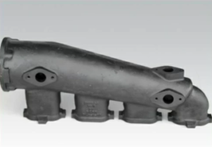
Exhaust Manifold for Detroit Diesel 8V71 and 16V71
This guide provides comprehensive torque specifications for all components in the exhaust and intake systems for Detroit Diesel V71 engine models, including both marine and non-marine applications. Fasteners in these systems must withstand high temperatures and thermal expansion while maintaining a tight, leak-free seal.
Exhaust and Intake Systems Torque Specifications
Component Torque Specification Notes Exhaust Manifold Bolts (8V71 & 16V71) 25–35 lb-ft (34–47 N•m) Tighten from the center outwards to prevent warping. Exhaust Manifold Bolts (6V71 & 12V71) 30–40 lb-ft (41–54 N•m) Use new gaskets to ensure a proper seal. Intake Manifold Bolts (All Models) 35–45 lb-ft (47–61 N•m) Use anti-seize compound for easier removal during future service. Turbocharger Mounting Bolts (If Equipped) 30–40 lb-ft (41–54 N•m) Ensure all surfaces are clean and free of debris before tightening. Turbocharger Oil Feed Line Banjo Bolt 20–25 lb-ft (27–34 N•m) Replace crush washers to avoid leaks. Turbocharger Oil Return Line Bolts 15–20 lb-ft (20–27 N•m) Ensure proper alignment to avoid gasket damage. Exhaust Elbow Mounting Bolts (Marine Only) 25–35 lb-ft (34–47 N•m) Tighten evenly to avoid leaks and ensure proper alignment. Intake Elbow Mounting Bolts 20–30 lb-ft (27–41 N•m) Use new gaskets and inspect surfaces for flatness. Exhaust Bellows Clamp 35–45 lb-in (4–5 N•m) Check for even tightening to avoid exhaust leaks. EGR (if applicable) Mounting Bolts 25–35 lb-ft (34–47 N•m) Use anti-seize compound to prevent seizing under high heat.
Assembly Best Practices
- Gasket Inspection: Always replace gaskets during reassembly and ensure all mating surfaces are flat and clean to prevent leaks.
- Tightening Sequence: For manifold installations, start tightening bolts from the center and work outwards to distribute stress evenly and avoid warping.
- Anti-Seize Use: Apply anti-seize compound to exhaust and intake manifold bolts to ease future disassembly, especially in high-temperature applications.
- Debris Check: Ensure that all mounting surfaces are free from debris, oil, and old gasket material before installation.
- Post-Installation Checks: After initial operation, inspect the exhaust and intake connections for leaks and re-torque if necessary.
- Thermal Expansion Consideration: Allow the engine to reach normal operating temperature and cool down once before final torque checks, especially on exhaust components.
- Lubrication of Threads: Lightly lubricate threads to achieve accurate torque values, unless otherwise specified.
- Gasket Inspection: Always replace gaskets during reassembly and ensure all mating surfaces are flat and clean to prevent leaks.
-
Detroit Diesel V71 Engines (6V71, 8V71, 12V71, 16V71) Timing Gear, Crankshaft, and Camshaft Torque Specifications

A technician removes the timing gears from a Detroit Diesel 2-cycle engine in order to get to the endplate.
This guide provides engine-specific torque specifications for the timing gear, crankshaft, and camshaft assembliesacross the Detroit Diesel V71 engine models. Precision in torque application is critical for maintaining proper engine timing, balance, and long-term durability.
Timing Gear, Crankshaft, and Camshaft Torque Specifications
Component 6V71 & 8V71 Specification 12V71 & 16V71 Specification Notes Crankshaft Pulley Bolt 275–325 lb-ft (373–441 N•m) 300–350 lb-ft (407–475 N•m) Use high-strength locking compound to prevent loosening. Crankshaft Main Gear Retaining Bolt 200–225 lb-ft (271–305 N•m) 225–250 lb-ft (305–339 N•m) Apply thread locker for secure gear retention. Crankshaft End Bolt (for Gear Retention) 220–250 lb-ft (298–339 N•m) 250–275 lb-ft (339–373 N•m) Ensure bolt is fully seated and secured. Crankshaft Thrust Plate Bolts 25–30 lb-ft (34–41 N•m) 30–35 lb-ft (41–47 N•m) Use thread sealant to prevent oil leaks. Timing Gear Cover Bolts 25–30 lb-ft (34–41 N•m) 30–35 lb-ft (41–47 N•m) Ensure proper alignment before torqueing. Gear Train Retaining Plate Bolts 25–30 lb-ft (34–41 N•m) 30–35 lb-ft (41–47 N•m) Tighten evenly to avoid misalignment. Flywheel Bolts 95–105 lb-ft (129–142 N•m) 105–115 lb-ft (142–156 N•m) Torque in a crisscross pattern using a locking compound. Vibration Damper Mounting Bolts 65–75 lb-ft (88–102 N•m) 70–80 lb-ft (95–108 N•m) Check alignment before final tightening. End Plate Mounting Bolts 25–30 lb-ft (34–41 N•m) 30–35 lb-ft (41–47 N•m) Replace gaskets if worn or damaged. Timing Pointer Mounting Bolts 15–20 lb-ft (20–27 N•m) 15–20 lb-ft (20–27 N•m) Confirm proper alignment for accurate timing verification.
Camshaft Assembly Torque Specifications
Component 6V71 & 8V71 Specification 12V71 & 16V71 Specification Notes Camshaft Gear Retaining Bolt 135–150 lb-ft (183–203 N•m) 150–165 lb-ft (203–224 N•m) Confirm gear is fully seated and aligned with timing marks. Camshaft Thrust Plate Bolts 25–30 lb-ft (34–41 N•m) 30–35 lb-ft (41–47 N•m) Use thread sealant to prevent oil leaks. Camshaft Bearing Cap Bolts 25–30 lb-ft (34–41 N•m) 30–35 lb-ft (41–47 N•m) Ensure correct orientation and even tightening. Idler Gear Shaft Retaining Bolt 85–95 lb-ft (115–129 N•m) 95–105 lb-ft (129–142 N•m) Check shaft for wear before installation. Blower Drive Gear Retaining Bolt 95–105 lb-ft (129–142 N•m) 105–115 lb-ft (142–156 N•m) Inspect gear teeth for wear and damage. Fuel Pump Drive Gear Retaining Bolt 95–105 lb-ft (129–142 N•m) 105–115 lb-ft (142–156 N•m) Use new lock washers for secure retention. Camshaft Timing Mark Alignment Visual Inspection Visual Inspection Confirm timing marks align with crankshaft and idler gear.
Assembly Best Practices
- Tightening Sequence: Always tighten bolts using a crisscross pattern to ensure even pressure and avoid component distortion.
- Thread Locking: Apply high-strength thread locker to critical bolts, including the crankshaft pulley bolt, camshaft gear retaining bolts, and flywheel bolts, to prevent loosening during operation.
- Camshaft Timing Alignment: Double-check timing marks on the crankshaft, camshaft, and idler gear to ensure proper alignment. Incorrect alignment can result in severe engine damage.
- Bearing Cap Orientation: Ensure camshaft bearing caps are installed correctly, and torque evenly to avoid distortion and improper lubrication.
- Lubrication: Apply assembly lubricant to all gear teeth, camshaft lobes, and bearing surfaces to ensure smooth initial operation and prevent wear.
- Post-Assembly Checks: After assembling the timing gear and camshaft components, manually rotate the crankshaft to verify proper operation and absence of binding.
- Gasket and Seal Inspection: Always replace worn or damaged gaskets and seals to prevent leaks. Pay particular attention to the timing gear cover and camshaft thrust plate.
- Re-Torque Procedure: After initial engine operation and heat cycles, recheck the torque on critical bolts to account for gasket settling and thermal expansion.
Cylinder Block & Related Components for Detroit Diesel V71 Engines
Crankshaft & Related Components for Detroit Diesel V71 Engines
Camshaft & Related Components for Detroit Diesel V71 Engines
Common Issues to Avoid
- Incorrect Timing Alignment: Misaligned timing marks can result in incorrect combustion timing, reduced performance, or severe engine damage.
- Over-Tightening Bolts: Excess torque can distort components like camshaft bearing caps, leading to improper lubrication and premature wear.
- Skipping Re-Torque Steps: Always recheck torque after initial operation to ensure fasteners remain secure under thermal stress.
- Dry Assembly: Always use proper lubrication during assembly to prevent early wear or damage during engine startup.
- Debris and Contaminants: Ensure that all mating surfaces are clean and free from debris or old gasket material before assembly.
- Tightening Sequence: Always tighten bolts using a crisscross pattern to ensure even pressure and avoid component distortion.
Explanation of Grade Identification and Material Strength for Bolts
Fasteners used in Detroit Diesel V71 engines are manufactured to strict specifications to ensure they can withstand the forces and temperatures experienced during engine operation. Understanding grade identification and material strength is essential for selecting the correct replacement fasteners or verifying the quality of existing ones.
-
Grade Identification of Bolts
The grade of a bolt is a measure of its tensile strength and is typically marked on the bolt head:
- Grade 5: Medium-strength bolts often used in low to moderate stress applications. Marked with three radial lines on the head.
- Grade 8: High-strength bolts used in critical engine components like cylinder heads and main bearings. Marked with six radial lines on the head.
- Metric Bolts: Identified by numbers like 8.8, 10.9, or 12.9, where higher numbers indicate greater tensile strength.
-
Material Strength and Properties
Bolts in the V71 engine are made from materials designed to resist corrosion, heat, and mechanical stress:
- Carbon Steel: Commonly used for general-purpose fasteners due to its strength and affordability.
- Alloy Steel: Offers higher strength and toughness, used for Grade 8 bolts and high-stress applications.
- Stainless Steel: Used in areas prone to corrosion, such as marine environments.
-
Importance of Material and Grade in Engine Applications
- Tensile Strength: Determines the maximum load a bolt can withstand without breaking. High-stress areas, such as cylinder heads, require high-tensile-strength bolts to prevent deformation under pressure.
- Heat Resistance: Fasteners in areas like the exhaust system must endure extreme temperatures without losing strength or becoming brittle.
- Corrosion Resistance: In marine engines, fasteners are exposed to saltwater and require materials like stainless steel or coated carbon steel to resist corrosion.
Best Practices for Torque Application
To ensure fasteners perform as intended, follow these best practices:
-
Use a Calibrated Torque Wrench:
- An uncalibrated wrench can lead to incorrect torque application, compromising fastener integrity.
- An uncalibrated wrench can lead to incorrect torque application, compromising fastener integrity.
-
Follow Manufacturer Specifications:
- Always use the specified torque value and tightening sequence to avoid uneven clamping forces.
- Always use the specified torque value and tightening sequence to avoid uneven clamping forces.
-
Lubricate Threads as Required:
- Some fasteners require lubrication to achieve accurate torque values. Use recommended lubricants to reduce friction.
- Some fasteners require lubrication to achieve accurate torque values. Use recommended lubricants to reduce friction.
-
Inspect Fasteners Before Use:
- Check for visible damage, such as cracks or corrosion. Replace any compromised fasteners.
- Check for visible damage, such as cracks or corrosion. Replace any compromised fasteners.
-
Recheck Torque After Initial Operation:
- Vibrations during engine operation can loosen fasteners. Recheck torque after the engine has been run for the first time.
- Vibrations during engine operation can loosen fasteners. Recheck torque after the engine has been run for the first time.
Summary
Proper torque application and the use of appropriate fasteners are foundational to the reliability of Detroit Diesel V71 engines. By adhering to the detailed torque tables and understanding the properties of fasteners, technicians can ensure the structural integrity, safety, and performance of these iconic engines. Neglecting torque specifications or using incorrect bolts can lead to engine failures, costly repairs, or safety hazards. Always consult this guide for accurate and reliable information.
Hi thanks for all the valuable info and will be dealing with you for sure in future purchases and info i have a marine x2 12v71 detroit tein turbo twin supercharges on each engine and someone replaced injectors recently and boat doesnt run the same , thinking that they didnt set injector timing correct? Would you be able to give me that info injector height , toming and exhaust vslve spec. The serial # and engine codes areRight side engine serial # 12VA-79123. 7122-7302.Left side engine serial#. 12VA-79058. 7102-3302 would you have specs on these engined that i have in my boat?injector height. Injector timing and exhaust valve clearence spec