

 Free US Calls: 1-888-433-4735
 International: 305-545-5588

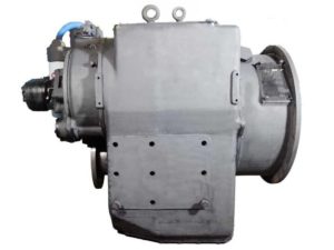
Introduction to Disassembly For Twin Disc MG-540 Marine Gear
The MG-540 marine transmission is a heavy-duty unit designed for long-term durability and high torque output. When disassembly is required—whether for overhaul, inspection, or replacement of internal components—it must be done in a clean, well-equipped facility by trained technicians. Proper disassembly ensures safe operation, preserves component integrity, and prepares the transmission for effective reassembly.
This guide outlines the complete disassembly process, focusing on:
- External component removal
- Input and output shaft disassembly
- Clutch shaft and pinion gear extraction
- Proper handling of seals, o-rings, and fasteners
- Recommended torque values and precautions
Important Note: Before disassembly, disconnect power and follow complete lockout/tagout procedures. Drain all fluids, and have appropriate lifting equipment available, as many components are heavy and precision-machined.
External Component Removal For Twin Disc MG-540 Marine Gear
Step 1: Drain the Transmission
- Drain the transmission oil by removing the 1-15/16″-12 hex plug from the bottom of the housing.
- Remove the drain plug from the bottom of the heat exchanger (if equipped) and allow full drainage of the system.
- Collect and dispose of used oil in accordance with marine environmental regulations.
Step 2: Disconnect External Lines and Hoses
- Label and disconnect hydraulic lines.
- If the unit uses the EC050 or electric valves, unplug solenoid wiring and sensors.
- Mark hoses and electrical connectors for ease during reassembly.
Step 3: Remove Filters and Heat Exchanger
- Remove the oil level dipstick and tube.
- Detach the high-pressure and lube oil filters by unscrewing their mounting bolts.
- Remove the heat exchanger if present.
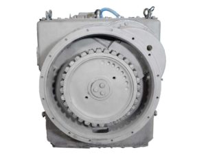
Step 4: Remove Top Cover and Oil Pumps
- Unscrew twenty-four 1/2-13 x 1.5 capscrews and remove the top cover.
- Remove the oil pumps (both pressure and lube) by removing their retaining capscrews.
Step 5: Rotate Transmission
- Use blocks to safely rotate the transmission with the input end facing upward.
- Confirm the transmission is securely blocked to prevent rolling or tipping.
Step-by-Step Disassembly of Input and Output Shaft Assemblies
Input Shaft and Gear Removal
- Remove Input Coupling: Flatten the lock plate and remove three 1/2-13 x 1.5 capscrews. Use a hydraulic puller to detach the coupling or rubber block drive from the tapered shaft.
- Remove Input Seal Retainer: Unscrew and remove the retainer using five 1/2-13 x 1.5 bolts.
- Remove Bearing Retainer: Remove the bearing retainer for the input driven gear using another set of five 1/2-13 bolts.
- Detach Front Input Housing: Remove seventeen 1/2-13 x 1.5 bolts holding the front input housing. Use jacking screws to carefully separate and remove the housing. Extract the lube valve from the front housing.
- Extract Input Gears: Remove both input driving and driven gears. Remove bearings only if they show signs of wear or failure.
Output Shaft Disassembly
- Remove Output Clamping Plate: Flatten the lock plate and remove three 1-14 x 2 bolts holding the output flange clamping plate.
- Remove Oil Catcher: Remove six 5/16-18 capscrews securing the output bearing oil catcher.
- Remove Bottom Cover: Unscrew twenty-four 1/2-13 capscrews from the bottom housing. Break the Loctite seal before lifting the cover.
- Extract Output Bearing Retainer: Remove the screw holding the outer race of the output bearing.
- Rotate Unit: Reposition the transmission so the output end faces up, and secure it.
- Remove Output Gear and Shaft:
- Use blocks to support the output gear before separating it.
- Use a hydraulic hollow ram and puller to remove the shaft from the taper. Up to 50 tons of force may be required.
- Remove bearings only if replacement is necessary.
Pinion Gear and Clutch Shaft Removal For Twin Disc MG-540 Marine Gear
Clutch Shaft Access and Disassembly
- Remove Suction Screens and Cover Assemblies: Remove the 3/8-16 capscrews to lift off the left and right cover assemblies and suction strainers.
- Remove Manifold and Pump Drive Adapters:
- Unscrew thirteen 1/2-13 and one 5/8-11 bolts to remove the rear manifold.
- Use a chisel to split the retaining sleeve on each clutch shaft.
- Drive out the retaining pin and remove the pump drive adapters from each clutch shaft.
- Remove Lube Tube: Lift out the lubrication tube and gasket.
- Withdraw Clutch Shaft Assemblies: Clutch shafts can now be removed and moved to a workbench or disassembled in place. If using a bench, use spring compressors (Tool T-16240-3) to disassemble the spring-loaded clutch piston.
Clutch Disassembly Steps
- Flatten lock tabs and remove twenty-four 1/2-13 x 6 bolts holding the retaining plate.
- Compress the spring with a press or special tool.
- Remove snap ring, spring, and retainers.
- Extract inner and outer pistons, clutch plates, and seal rings.
- If required, remove the bearing cone from the cylinder.
- Remove clutch plates and backplate from transfer gear.
Pinion Gear Removal
- Flatten screw locks and remove six 1/2-13 x 4.5 bolts that hold the pinion bearing caps.
- Use jacking bolts to remove caps, then remove bearing cups.
- Install special tool T-16240-4 to remove the pinion and hub assembly.
- Remove retaining rings, shims, and oil catchers as needed.
Proper Handling of Seals, O-Rings, and Torque Specs For Twin Disc MG-540 Marine Gear
Seal and O-Ring Removal and Replacement
- All seals, o-rings, and gaskets must be discarded and replaced during reassembly.
- Tag and store old components with associated parts to track quantity and type.
- Use Twin Disc-approved replacements and lubricate all o-rings lightly with clean transmission oil before installation.
O-Ring Tips:
- Avoid twisting during installation.
- Do not reuse any rubber sealing component.
- Use plastic or wood tools—never metal picks—to remove o-rings.
Torque Specifications
Correct torque is critical to prevent component warping, fastener stretching, and premature failure. Refer to the following fastener torque chart for U.S. Standard threads:
| Thread Diameter | SAE Grade 5 Torque (lb-ft) | SAE Grade 8 Torque (lb-ft) |
| 1/4″ | 6–8 | 10–12 |
| 3/8″ | 25–29 | 35–41 |
| 1/2″ | 60–70 | 83–97 |
| 5/8″ | 120–140 | 165–195 |
| 3/4″ | 205–245 | 295–345 |
| 1″ | 495–585 | 715–835 |
All threads must be lubricated with a light film of oil prior to torquing.
Best Practices:
- Use a calibrated torque wrench
- Torque bolts in a criss-cross pattern when securing housings or covers
- Document torque values and part replacements in maintenance logs
Conclusion
Disassembly of the Twin Disc MG-540 marine gear is an intensive process requiring attention to detail, proper tools, and methodical procedures. Every seal, shim, and fastener plays a role in transmission performance and safety. This section covered:
- Safe and complete external component removal
- Step-by-step disassembly of shafts, clutches, and gears
- Precision handling of seals and fasteners
- Torque best practices and tool recommendations
When executed correctly, this disassembly lays the groundwork for a successful inspection and eventual rebuild or reassembly. Always consult the OEM tolerances and use approved replacement parts to ensure continued reliability at sea.
Videos About Twin Disc Transmissions
6 Reasons Your Twin Disc Transmission Has Low Oil Pressure
7 Reasons Your Twin Disc Transmission Is Overheating
3 Reasons Your Clutch Plates in Your Twin Disc Transmission Are Making Excessive Noise
Bull Gear On A Twin Disc Transmission
Rebuilt Twin Disc Transmissions