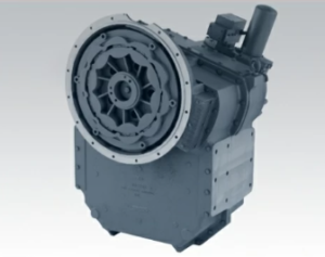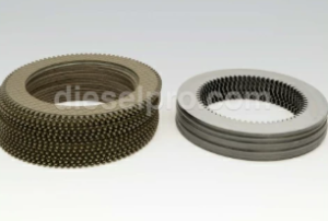
Disassembling the Twin Disc MG520 Marine Gear is not a casual task—it is a structured, critical process that demands precision, planning, and safety. Whether you’re performing a routine internal inspection, a clutch pack rebuild, or a full overhaul, knowing how to systematically disassemble this transmission is essential to ensuring a successful service and reassembly later.
In this section, we walk through the complete disassembly process in detail. This includes pre-disassembly documentation and labeling, removal of auxiliary connections, and a component-by-component teardown of the input section, output shaft, reduction gear assembly, and clutch pack.
⚠️ Important Note: Always refer to the OEM Twin Disc MG520 Service Manual for internal clearance tolerances, bolt torque values, and wear limits. This guide is a practical outline, but precise specifications should be verified against the manufacturer’s documentation.

Parts Catalog for Twin Disc MG520 Marine Transmissions
Rebuilt Twin Disc MG520 Marine Transmissions
Plate Kit For Twin Disc MG520 Marine Transmission
Gasket Kits For Twin Disc MG520 Marine Transmission
Initial Preparation For Twin Disc MG520 Marine Gear
Proper disassembly begins before you touch a single bolt. The initial steps ensure your work is clean, documented, and traceable—which is especially important in complex rebuilds or commercial operations.
1. Marking and Documentation Before Removal
Why It Matters:
The MG520 is made up of multiple shafts, clutches, planetary or reduction gearsets, and hydraulic passages. Once disassembled, these parts may appear similar—but subtle differences in orientation, shimming, or rotation are critical to its function.
Best Practices:
- Photograph Everything
- Before removing anything, take multiple photos from different angles.
- Label each photo by component group: input, output, control housing, reduction section, etc.
- Include close-ups of control valves, wiring harnesses, and oil routing.
- Use Component Tags
- Use non-damaging tags or masking tape to label:
- Hydraulic hoses
- Electrical connectors
- Shift cables
- Coolant/oil lines
- Mark both ends of the connection to ease reinstallation.
- Paint or Punch Alignment Marks
- Use a paint pen or punch to create reference marks on:
- Couplings to flanges
- Gear housings and intermediate covers
- Input shaft to flywheel adapter
- These marks ensure proper clocking and alignment during reassembly.
- Record Initial Measurements
- If possible, use a dial indicator to measure:
- Output shaft endplay
- Input shaft free play
- Gear backlash
- Record these baseline numbers in a service log.
2. Removal of Associated Linkages, Hoses, and Wiring
Before removing the transmission, all external attachments must be safely disconnected. Failure to do so can result in damaged fittings, wiring, or control systems.
Step-by-Step Disconnect Checklist:
- Electrical Wiring (if EC300-equipped):
- Shut off power at the main battery switch.
- Disconnect the ECU connectors and label each plug.
- Remove cable ties and support brackets holding the harness to the housing.
- Hydraulic Lines:
- Identify supply and return lines to the clutch valve body.
- Drain the hydraulic reservoir or isolate valves before removal.
- Use caps and plugs on open ends to prevent contamination.
- Oil Cooler Hoses:
- These lines carry lube oil to and from the gear oil cooler.
- Disconnect both lines, drain excess oil into pans.
- Label inlet vs. outlet to ensure correct flow during reassembly.
- Control Linkages (if mechanical):
- Disconnect control levers and clevis pins from the selector shaft.
- Inspect for wear or looseness.
- PTO or Auxiliary Attachments:
- If your MG520 has a hydraulic PTO, remove hydraulic lines and the PTO housing separately.
- Be cautious of residual pressure or attached equipment such as pumps.
- Output Coupling:
- Unbolt the output flange or coupling from the propeller shaft.
- Support the shaft to avoid strain on the stern bearing or stuffing box.
- If possible, retract the shaft slightly for clearance.
Tips for a Clean Disassembly Environment:
- Use drip trays and absorbent mats under all hose connections.
- Keep a separate tray or container for bolts and fittings from each section.
- Wipe down each component as it’s removed to avoid spreading contamination.
Component Disassembly For Twin Disc MG520 Marine Gear
Once the MG520 is free of external connections and safely hoisted onto a workbench or support cradle, the step-by-step internal disassembly can begin. The components below are listed in order of typical removal.
1. Input Section
The input section houses the input shaft, damper coupling, and connection to the engine flywheel. It is the first major area to disassemble.
Disassembly Steps:
- Remove the Input Coupling or Drive Plate
- Unbolt the coupling from the flywheel adapter or flex plate.
- Inspect the splines for wear, galling, or fretting corrosion.
- Unbolt and Remove the Input Cover
- Loosen bolts in a crisscross pattern to avoid warping.
- Use a plastic mallet if necessary to gently free the cover.
- Withdraw the Input Shaft
- The input shaft may need to be tapped free if it’s tight in the pilot bearing.
- Slide out slowly to avoid damaging oil seals or shaft splines.
- Inspect Input Bearings and Seals
- Remove the input shaft bearing if replacement is needed.
- Inspect the input oil seal—this is a common leak point.
Inspection Points:
- Shaft spline wear
- Shaft straightness (check on v-blocks)
- Bearing condition (spin by hand for roughness)
- Seal wear or hardening
2. Output Shaft
The output shaft connects the internal clutch and gear train to the propeller shaft and transmits all final drive torque.
Disassembly Steps:
- Remove the Output Flange
- Unbolt and slide off the output coupling or yoke.
- Use a puller if the flange is pressed on.
- Remove the Output Cover
- This often includes the rear bearing support.
- Remove bolts evenly and support the cover to prevent sudden drops.
- Withdraw the Output Shaft
- Slide the shaft straight out, being cautious of gear mesh resistance.
- Avoid damaging internal gears or clutch hubs during removal.
Inspection Points:
- Check for shaft scoring or heat marks
- Inspect keyways and threads
- Spin and test rear bearing
- Check rear seal condition
- Measure shaft runout using dial indicator
3. Reduction Gear Section

This section reduces engine RPMs to usable propeller speeds. It may be planetary or parallel gear depending on MG520 configuration.
Disassembly Steps:
- Unbolt the Gear Housing Cover
- These bolts are typically larger and under torque; use breaker bar.
- Support the cover during removal to avoid straining gear teeth.
- Extract the Gear Set
- Gears may include idler, planetary, or driven gears.
- Remove any retaining rings or alignment pins.
- Inspect the Gear Teeth
- Look for pitting, spalling, or chipped edges.
- Clean with solvent to view fine cracks.
- Remove Associated Bearings
- Use a puller for press-fit bearings.
- Check for heat discoloration or metal flake buildup.
Inspection Points:
- Backlash tolerance (measure with feeler gauge)
- Tooth profile wear
- Bearing preload or axial play
- Housing damage or fretting
4. Clutch Pack

The clutch pack is the heart of the MG520, responsible for engaging forward or reverse through hydraulic pressure.
Disassembly Steps:
- Access the Clutch Drum
- Remove the control valve body or shift piston cover.
- Drain any residual oil before proceeding.
- Remove Snap Rings or Retainers
- Use snap ring pliers—some may be spiral-type and require patience.
- Use snap ring pliers—some may be spiral-type and require patience.
- Slide Out the Clutch Plates
- Alternate steel and friction plates
- Keep them in order for reference
- Inspect Clutch Piston and Springs
- Remove piston carefully; springs may be compressed
- Remove piston carefully; springs may be compressed
Inspection Points:
- Friction plate thickness (measure with calipers)
- Warped or heat-checked steel plates
- Burnt friction material (indicates slippage)
- Broken return springs or piston seals
- End clearance of the clutch pack
⚠️ Reassembly Notes
As each component is removed, store it carefully and label it by section. Before reassembly:
- Clean all gasket surfaces with non-marring scrapers.
- Store bearings and seals in a clean, dry place.
- Photograph any shims or washers used for preload.
Conclusion: Disassembly Requires Discipline and Detail For Twin Disc MG520 Marine Gear
Disassembling the Twin Disc MG520 is a methodical and high-precision task. Every bolt removed and part extracted should be documented, inspected, and stored with care. By following the preparation, labeling, and teardown strategies in this guide, you’ll set yourself up for a smooth and confident reassembly later.
Remember, the service manual is not optional—it’s your reference for every clearance, torque spec, and test value. And when you’re ready for reassembly or parts replacement, Diesel Pro Power is your trusted source for MG520 overhaul kits, clutch packs, seals, and expert support.

Rebuilt Twin Disc MG520 Marine Transmissions
Plate Kit For Twin Disc MG520 Marine Transmission
Gasket Kits For Twin Disc MG520 Marine Transmission
Videos About Twin Disc Transmissions
6 Reasons Your Twin Disc Transmission Has Low Oil Pressure
7 Reasons Your Twin Disc Transmission Is Overheating
3 Reasons Your Clutch Plates in Your Twin Disc Transmission Are Making Excessive Noise
Bull Gear On A Twin Disc Transmission
Rebuilt Twin Disc Transmissions


 Free US Calls: 1-888-433-4735
 International: 305-545-5588