

 Free US Calls: 1-888-433-4735
 International: 305-545-5588

Alternator and Starter Maintenance | ECM and Sensor Diagnostics
The electrical system in Cummins ISM, ISMe, and QSM11 engines is essential for engine operation, performance monitoring, and diagnostics. The alternator, starter motor, Electronic Control Module (ECM), and various sensorsensure reliable engine performance by supplying electrical power, starting the engine efficiently, and providing real-time data to optimize fuel efficiency and emissions control.
A failing alternator, starter, or ECM-related issue can lead to hard starts, battery drainage, performance loss, or even complete engine shutdown. Regular inspection, troubleshooting, and preventive maintenance are essential to keep the electrical system functioning optimally.
This guide provides a detailed step-by-step process for maintaining the alternator, servicing the starter motor, diagnosing ECM and sensor issues, and troubleshooting common electrical faults in Cummins ISM, ISMe, and QSM11 engines.
For specific torque values, voltage specifications, and diagnostic procedures, consult an OEM service manual or contact Diesel Pro Power for expert assistance.
Parts Catalog for ISM Cummins Marine and Industrial Engines
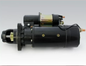
Starter & Related Components for Cummins ISM Engine
Parts Catalog for QSM11 Cummins Marine and Industrial Engines
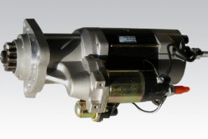
Starter & Related Components for Cummins QSM11 Engine
Alternator and Starter Maintenance for Cummins ISM, ISMe, and QSM11

The alternator and starter are crucial electrical components that ensure reliable starting and continuous power supplyto essential systems.
Key Components of the Charging and Starting System
✔ Alternator – Generates electrical power to recharge the battery and run electrical systems.
✔ Starter Motor – Provides the initial rotation to crank the engine.
✔ Battery – Supplies power to the starter and stabilizes electrical flow.
✔ Voltage Regulator – Maintains proper voltage levels in the charging system.
✔ Starter Solenoid – Engages the starter motor when the ignition key is turned.
✔ Grounding System – Ensures stable electrical connections throughout the vehicle.
How the Charging and Starting System Works
- Battery Supplies Power
- When the ignition key is turned, the battery sends power to the starter solenoid.
- When the ignition key is turned, the battery sends power to the starter solenoid.
- Starter Motor Engages
- The starter motor turns the flywheel, cranking the engine.
- The starter motor turns the flywheel, cranking the engine.
- Alternator Begins Charging
- Once running, the alternator recharges the battery and supplies power to electrical systems.
- Once running, the alternator recharges the battery and supplies power to electrical systems.
- Voltage Regulator Controls Output
- The voltage regulator ensures the battery and components receive the correct voltage.
- The voltage regulator ensures the battery and components receive the correct voltage.
Common Alternator and Starter Issues
A failing alternator or starter motor can result in hard starting, battery drainage, or loss of electrical power.
| Symptom | Possible Cause | Recommended Action |
| Dim or Flickering Lights | Failing alternator, loose connections | Test alternator output, check wiring |
| Slow Cranking or No Start | Weak battery, faulty starter motor | Check battery charge, inspect starter solenoid |
| Battery Not Charging | Worn alternator brushes, broken belt | Test alternator, replace belt if needed |
| Clicking Sound When Starting | Faulty starter solenoid, bad battery cables | Inspect starter circuit, test battery |
| Electrical System Malfunctions | Grounding issues, ECM communication error | Check ground wires, scan ECM for faults |
Step 1: Inspecting and Testing the Alternator
- Check Battery Voltage with Engine Off and Running
- Use a multimeter to measure battery voltage:
- 12.6V-12.8V (Engine Off) – Fully charged battery
- 13.8V-14.5V (Engine Running) – Proper alternator function
- Use a multimeter to measure battery voltage:
- Inspect Alternator Belt and Connections
- Check the serpentine belt for wear, cracks, or misalignment.
- Ensure battery terminals are clean and securely attached.
- Test Alternator Output with a Load
- Turn on headlights, AC, and blower fan while measuring voltage.
- If voltage drops below 13V, the alternator may be failing.
Step 2: Replacing the Alternator
- Disconnect the Battery to Prevent Shorts
- Remove the negative (-) terminal first, then the positive.
- Remove the negative (-) terminal first, then the positive.
- Unbolt and Remove the Old Alternator
- Loosen the belt tensioner and remove the belt from the alternator pulley.
- Unbolt the alternator from its mounting bracket.
- Install the New Alternator and Reconnect Wiring
- Torque mounting bolts to OEM specifications.
- Reinstall the belt and adjust tension properly.
- Reconnect the Battery and Test Charging Output
- Start the engine and verify voltage levels are within range.
- Start the engine and verify voltage levels are within range.
Step 3: Inspecting and Servicing the Starter Motor
- Perform a Starter Draw Test
- Use a starter load tester to measure cranking amperage.
- Compare readings with OEM specifications.
- Inspect the Starter Solenoid and Wiring
- Look for corrosion or loose connections at the solenoid terminals.
- If clicking occurs but the engine doesn’t turn over, the solenoid may be faulty.
- Check for Excessive Heat on Starter Motor
- If the starter feels extremely hot, it may be drawing too much current.
- If the starter feels extremely hot, it may be drawing too much current.
Step 4: Replacing a Faulty Starter Motor
- Disconnect the Battery
- Always disconnect the negative (-) cable first.
- Always disconnect the negative (-) cable first.
- Remove the Starter Motor Bolts
- Support the starter while removing bolts to prevent damage.
- Support the starter while removing bolts to prevent damage.
- Install the New Starter Motor
- Torque bolts to OEM specifications.
- Torque bolts to OEM specifications.
- Reconnect Battery and Test Engine Start
- Turn the ignition key and verify proper cranking speed.
- Turn the ignition key and verify proper cranking speed.
ECM and Sensor Diagnostics for Cummins ISM, ISMe, and QSM11
The Electronic Control Module (ECM) and engine sensors are responsible for monitoring and optimizing engine performance, fuel efficiency, and emissions control. A faulty ECM or sensor can lead to poor engine response, excessive fuel consumption, and warning lights on the dashboard.
Key Components of the ECM and Sensor System
✔ ECM (Electronic Control Module) – Controls fuel injection, timing, and emissions.
✔ Crankshaft and Camshaft Position Sensors – Ensure proper engine timing.
✔ Mass Air Flow (MAF) Sensor – Measures air entering the engine for correct fuel delivery.
✔ Coolant Temperature Sensor – Prevents overheating by adjusting fuel and cooling.
✔ Manifold Absolute Pressure (MAP) Sensor – Regulates turbo boost pressure.
Common ECM and Sensor Issues
Symptom |
Possible Cause |
Recommended Action |
| Check Engine Light (CEL) On | Faulty sensor, ECM error, bad wiring | Scan for fault codes, inspect wiring |
| Loss of Power | Malfunctioning MAP sensor, fuel system issue | Test MAP sensor, check fuel pressure |
| Hard Starting or Stalling | Crankshaft/camshaft position sensor failure | Inspect and replace sensor |
| High Fuel Consumption | Incorrect air/fuel ratio due to sensor failure | Test MAF sensor, scan ECM for codes |
Step 1: Scanning the ECM for Fault Codes
- Use a Cummins INSITE™ or OBD-II Scanner
- Retrieve Diagnostic Trouble Codes (DTCs) from the ECM.
- Cross-check codes with OEM service manuals.
- Check Live Data from Sensors
- Monitor real-time data for irregular readings in air, fuel, and timing parameters.
- Monitor real-time data for irregular readings in air, fuel, and timing parameters.
Step 2: Inspecting and Testing Sensors
- Test the MAP Sensor
- Use a multimeter to measure voltage at the sensor terminals.
- Compare readings with OEM pressure specifications.
- Inspect the Crankshaft and Camshaft Position Sensors
- Check for oil contamination or damage on the sensor connectors.
- Check for oil contamination or damage on the sensor connectors.
- Test the Coolant Temperature Sensor
- If the ECM is reading incorrect engine temperatures, replace the sensor.
- If the ECM is reading incorrect engine temperatures, replace the sensor.
Final Notes on Electrical Equipment Maintenance for Cummins ISM, ISMe, and QSM11
✔ Inspect and test alternator and starter regularly.
✔ Monitor ECM and sensors for performance issues.
✔ Use high-quality batteries and ensure proper grounding connections.
✔ Scan ECM for error codes and perform diagnostics if symptoms arise.
✔ Consult Diesel Pro Power for expert guidance and replacement parts.
By following these detailed procedures, you ensure optimal electrical system performance, improved reliability, and extended service life for Cummins ISM, ISMe, and QSM11 engines.
Parts Catalog for ISM Cummins Marine and Industrial Engines
Starter & Related Components for Cummins ISM Engine
Parts Catalog for QSM Cummins Marine and Industrial Engines
Starter & Related Components for Cummins QSM11 Engine