

 Free US Calls: 1-888-433-4735
 International: 305-545-5588
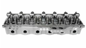
Cylinder Block and Cylinder Head Components For Detroit Diesel Series 60 Engines (11.1L, 12.7L, 14L)
Overview
The cylinder block and cylinder head form the backbone of the Detroit Diesel Series 60 engine. These components house critical assemblies such as pistons, connecting rods, valves, and injectors. Precision machining and robust construction ensure their reliability under demanding conditions. Proper handling during removal, inspection, and reassembly is essential to maintain engine integrity.
Parts Catalog for 11.1L Detroit Diesel 60 Series Marine Engine
Parts Catalog for 12.7L Detroit Diesel 60 Series Marine Engine
Parts Catalog for 14L Detroit Diesel 60 Series Marine Engine
Removal and Inspection
Cylinder Block Removal
- Drain all fluids, including coolant and oil.
- Disconnect the fuel, cooling, and lubrication systems.
- Use an engine hoist to carefully remove the engine assembly from the chassis.
- Separate ancillary components such as the oil pan, flywheel housing, and mounts.
Inspection Checklist
- Surface Integrity: Examine the cylinder block and head for cracks, warping, and scoring.
- Oil and Coolant Passages: Ensure passages are clear of obstructions and corrosion.
- Cylinder Liners: Measure wear and check for scoring or pitting. Replace liners if the wear exceeds tolerances.
- Threads: Inspect threaded holes for damage, re-tap if necessary.
Reassembly Procedures
- Clean Components: Thoroughly clean all parts to remove contaminants.
- Install Cylinder Liners: Use an appropriate press tool, ensuring liners are seated firmly. Verify liner protrusion matches specifications.
- Torque Specifications: Adhere to torque values during reassembly, especially for critical components like head bolts.
- Sealants and Gaskets: Use high-quality sealants and gaskets to prevent leaks.
The gear train of the Detroit Diesel Series 60 engine is a crucial system that synchronizes the movement of vital components. Its primary function is to transfer power from the crankshaft to other essential systems, such as the camshaft, fuel pump, and oil pump, ensuring precise timing for valve operation and fuel injection. The compact gear train design offers enhanced durability and efficient lubrication, contributing to the engine’s overall reliability and performance. Proper alignment and gear lash adjustment are critical for maintaining optimal performance and avoiding premature wear or failure.
Compact Gear Train Overview

The compact gear train is located at the front of the engine and operates within a fully enclosed housing. This design provides protection from contaminants and ensures the gears are continuously lubricated by oil splash. The gear train comprises the following components:
- Crankshaft Timing Gear: Drives the bull gear and oil pump drive gear directly.
- Bull Gear: Transfers motion from the crankshaft gear to the camshaft gear, air compressor, and accessory gears.
- Camshaft Drive Gear: Controls the camshaft, which in turn operates the engine’s intake and exhaust valves, as well as the fuel injectors.
- Idler Gear: Acts as an intermediary between the crankshaft gear and the camshaft gear, ensuring proper timing.
- Oil Pump Drive Gear: Ensures the circulation of oil for lubrication and cooling.
Timing Mark Alignments
Accurate alignment of timing marks on the gear train is essential for proper engine operation. Misalignment can result in performance issues, including poor combustion, loss of power, or engine damage.
Steps for Aligning Timing Marks
- Initial Positioning:
- Rotate the crankshaft using a ratchet or breaker bar until the timing marks on the crankshaft gear and bull gear align.
- Ensure the camshaft timing mark aligns with the corresponding mark on the bull gear.
- Idler Gear Positioning:
- Confirm the idler gear’s timing marks correspond with the timing marks on the crankshaft and camshaft gears.
- Use a straightedge to verify that all marks are correctly aligned.
- Visual Verification:
- Double-check the alignment of all marks. Use a flashlight to ensure marks are visible and clearly matched.
- Rotate the crankshaft through two complete revolutions and verify that all marks realign perfectly.
Adjusting Gear Lash
Gear lash refers to the small clearance between mating gear teeth. Proper gear lash is vital for reducing noise, ensuring efficient operation, and preventing excessive wear or overheating. The acceptable gear lash range for the Detroit Diesel Series 60 engine is 0.051–0.229 mm (0.002–0.009 in.).
Importance of Gear Lash
- Excessive Gear Lash: Causes increased vibration, gear noise, and potential damage to gear teeth.
- Insufficient Gear Lash: Leads to overheating, accelerated wear, and binding of the gear train.
Measuring Gear Lash
- Prepare for Measurement:
- Install a magnetic base dial indicator near the gear housing.
- Position the indicator tip on the face of a gear tooth to detect movement.
- Measure Lash:
- Hold the driven gear stationary and gently rock the driving gear back and forth.
- Record the total movement displayed on the dial indicator.
- Check Multiple Positions:
- Rotate the crankshaft to measure lash at four positions, spaced 90 degrees apart, for consistency.
Adjusting Gear Lash
- Shim Adjustment:
- Add or remove shims between the gear housing and the engine block to modify the gear lash.
- Adding shims increases lash, while removing shims decreases it.
- Recheck Measurements:
- After adjustments, re-measure the lash to ensure it falls within the specified range of 0.051–0.229 mm (0.002–0.009 in.).
- After adjustments, re-measure the lash to ensure it falls within the specified range of 0.051–0.229 mm (0.002–0.009 in.).
- Final Verification:
- Rotate the crankshaft to ensure smooth operation and consistent gear movement without binding or excessive play.
Common Gear Train Issues and Troubleshooting
The gear train can develop issues over time due to wear, improper adjustments, or component damage. Regular inspections and maintenance are necessary to identify and address these problems early.
Gear Train Noise
- Excessive Noise:
- Cause: Excessive gear lash, worn gear teeth, or misaligned gears.
- Solution: Inspect the gear train for wear or damage and adjust the gear lash as needed. Replace damaged gears.
- Whining Sound:
- Cause: Insufficient gear lash or excessive bearing preload.
- Solution: Adjust gear lash to within the acceptable range and check for bearing wear.
Gear Wear or Damage
- Chipped or Pitted Teeth:
- Cause: Contamination, insufficient lubrication, or prolonged misalignment.
- Solution: Replace damaged gears and flush the lubrication system to remove contaminants.
- Gear Housing Leaks:
- Cause: Worn seals or improper torque on housing bolts.
- Solution: Replace seals and torque bolts to specifications.
Inspection and Maintenance
Regular inspection of the gear train ensures optimal performance and extends the lifespan of engine components. The following practices are recommended during routine maintenance or engine overhauls:
Visual Inspection
- Inspect Gear Teeth:
- Look for signs of wear, cracks, or chips on gear teeth.
-
Check Alignment:
- Verify that all timing marks are aligned correctly.
- Verify that all timing marks are aligned correctly.
- Inspect Bearings and Bushings:
- Check for excessive wear or looseness in gear bearings and bushings. Replace as needed.
- Check for excessive wear or looseness in gear bearings and bushings. Replace as needed.
Lubrication System Maintenance
- Oil Supply:
- Ensure adequate oil flow to the gear train. Inspect oil passages for blockages or leaks.
- Ensure adequate oil flow to the gear train. Inspect oil passages for blockages or leaks.
- Oil Quality:
- Use recommended oil grades and change oil at specified intervals to prevent contamination and gear wear.
Reassembly Tips
After completing inspections, repairs, or adjustments, reassemble the gear train carefully to ensure proper operation.
- Apply Torque Specifications:
- Use a calibrated torque wrench to tighten bolts to the manufacturer’s specifications.
- Use a calibrated torque wrench to tighten bolts to the manufacturer’s specifications.
- Use New Seals and Gaskets:
- Always replace seals and gaskets during reassembly to prevent oil leaks.
- Always replace seals and gaskets during reassembly to prevent oil leaks.
- Final Testing:
- Rotate the crankshaft through multiple revolutions to verify smooth gear operation and proper timing alignment.
Conclusion
The gear train of the Detroit Diesel Series 60 engine plays a pivotal role in the precise operation of engine components. Proper alignment of timing marks, accurate adjustment of gear lash, and thorough inspections are essential to maintain engine performance and reliability. By following the procedures outlined in this guide, mechanics can ensure the gear train functions optimally, minimizing downtime and preventing costly repairs.
For high-quality aftermarket parts designed to meet or exceed OEM specifications, Diesel Pro Power offers a comprehensive range of replacement components for Detroit Diesel Series 60 engines.
Replacement of Components
Proper inspection and replacement of worn or damaged gear train components are critical to maintaining the performance and reliability of the Detroit Diesel Series 60 engine. The gear train drives essential systems such as the camshaft, oil pump, and fuel pump, and its precision directly impacts engine timing and efficiency. This section provides detailed guidance on identifying issues, replacing components, and reassembling the gear train to factory specifications.
Inspection of Gear Train Components
Gear Condition
- Visual Inspection:
- Examine all gear teeth for signs of pitting, chipping, or excessive wear.
- Look for discoloration or heat marks, which may indicate insufficient lubrication or overheating.
- Check for burrs, cracks, or deformities on gear surfaces.
- Measurements:
- Use a micrometer or caliper to measure the thickness and uniformity of gear teeth.
- Compare measurements to the manufacturer’s specifications to determine if gears are within tolerances.
- Common Issues:
- Pitting: Indicates prolonged operation under high stress or inadequate lubrication.
- Chipping: Often caused by debris in the gear housing or improper lash adjustments.
- Excessive Wear: Results from misalignment, insufficient lubrication, or extended service life.
Bearings
- Inspection for Play:
- Wiggle each bearing manually to detect excessive movement.
- Bearings with noticeable play should be replaced, as they may compromise gear alignment.
- Noise Check:
- Spin the bearings and listen for grinding or irregular noises, which indicate wear or damage.
- Spin the bearings and listen for grinding or irregular noises, which indicate wear or damage.
- Surface Examination:
- Inspect bearing races for scoring, spalling, or pitting.
- Replace any bearings that show signs of wear, as these defects can lead to vibration and premature failure.
Additional Components
- Idler Gear Bushings: Check for ovality or wear in bushings that can cause misalignment.
- Seals and Gaskets: Inspect for leaks or signs of degradation. Always replace seals and gaskets during reassembly.
Replacement of Damaged Components
Gears
- Preparation:
- Ensure the engine is properly supported and components are free of contaminants.
- Remove any oil or debris from the gear train housing.
- Removal:
- Use a gear puller to carefully remove the damaged gear without applying uneven force.
- Avoid damaging adjacent components during the removal process.
- Installation:
- Align the new gear with the appropriate timing marks and ensure a snug fit on the shaft.
- Apply a light coat of assembly lubricant to gear surfaces to reduce wear during initial operation.
- Verification:
- Rotate the gear manually to ensure smooth operation and alignment with mating gears.
- Rotate the gear manually to ensure smooth operation and alignment with mating gears.
Bearings
- Removal:
- Use a bearing puller or press to extract worn or damaged bearings.
- Ensure the removal process does not damage the surrounding housing or shafts.
- Installation:
- Press-fit new bearings into their respective housings using a hydraulic or manual press.
- Confirm that the bearings are seated evenly and securely.
- Post-Installation Check:
- Verify that the new bearings rotate freely without play or noise.
- Verify that the new bearings rotate freely without play or noise.
Seals and Gaskets
- Removal:
- Remove old seals carefully to avoid scoring the housing or shaft.
- Clean the sealing surfaces thoroughly to remove residue and debris.
- Installation:
- Apply a thin layer of sealant or petroleum jelly to the seal edges.
- Press the new seal into place evenly, ensuring a proper fit.
Reassembly
Reassembling the gear train requires precision to ensure proper alignment and functionality.
- Align Timing Marks:
- Position all gears according to the timing marks to maintain synchronization.
- Verify alignment with a straightedge or alignment tool.
- Reinstall Gear Train Components:
- Follow the reverse order of removal for reassembly.
- Torque all fasteners to the manufacturer’s specifications to avoid over-tightening or loosening during operation.
- Check Gear Lash:
- Measure the gear lash using a dial indicator at multiple points on each gear.
- Ensure lash is within the specified range (0.051–0.229 mm / 0.002–0.009 in.).
- Lubrication:
- Apply assembly lube to all moving parts and ensure the lubrication system is functioning correctly.
- Apply assembly lube to all moving parts and ensure the lubrication system is functioning correctly.
- Install Housing and Seals:
- Replace the gear train cover and secure it with the proper torque sequence.
- Double-check all seals to prevent oil leaks.
Final Checks and Testing
Rotation Check
- Manual Rotation:
- Rotate the crankshaft manually through multiple revolutions.
- Observe the operation of the gear train for smoothness and proper alignment.
- Noise Detection:
- Listen for any unusual noises such as grinding or rattling, which may indicate misalignment or insufficient lubrication.
- Listen for any unusual noises such as grinding or rattling, which may indicate misalignment or insufficient lubrication.
Engine Testing
- Start-Up Inspection:
- Start the engine and monitor the operation of the gear train.
- Check for leaks, vibrations, or abnormal noises.
- Oil Pressure Check:
- Confirm that the oil pressure is within the specified range to ensure proper lubrication of the gear train.
- Confirm that the oil pressure is within the specified range to ensure proper lubrication of the gear train.
- Recheck Timing Marks:
- Shut off the engine and re-inspect timing marks to verify they remain aligned after operation.
Common Mistakes to Avoid
- Skipping Timing Mark Verification:
- Misaligned timing marks can lead to poor engine performance or catastrophic failure. Always double-check alignment.
- Misaligned timing marks can lead to poor engine performance or catastrophic failure. Always double-check alignment.
- Improper Torque Application:
- Over-tightening bolts can damage components, while under-tightening can lead to loosening during operation. Use a calibrated torque wrench.
- Over-tightening bolts can damage components, while under-tightening can lead to loosening during operation. Use a calibrated torque wrench.
- Reusing Old Seals:
- Worn seals may leak after reassembly. Always replace seals and gaskets to ensure a leak-free system.
- Worn seals may leak after reassembly. Always replace seals and gaskets to ensure a leak-free system.
- Neglecting Gear Lash Adjustment:
- Failure to adjust gear lash can result in excessive noise, vibration, or premature gear failure.
Tools and Equipment Required
- Gear puller and bearing press.
- Dial indicator with a magnetic base.
- Torque wrench and alignment tools.
- Assembly lubricant and sealant.
- Cleaning supplies, such as solvents and compressed air.
Conclusion
Replacing components in the gear train of the Detroit Diesel Series 60 engine requires meticulous attention to detail and adherence to manufacturer specifications. Regular inspections, accurate adjustments, and the use of high-quality replacement parts are essential to ensure the longevity and performance of the gear train.
For premium aftermarket components that meet or exceed OEM standards, trust Diesel Pro Power to supply the parts you need for reliable engine maintenance and repair.
Camshaft and Associated Assemblies For Detroit Diesel 60 Series Engines (11.1L, 12.7L, 14L)
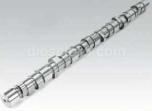
The camshaft and its associated assemblies are integral to the operation of the Detroit Diesel Series 60 engine. They ensure proper valve timing, injector operation, and synchronization with the gear train. This section details the components of the camshaft assembly, removal and installation procedures, timing and alignment techniques, and an inspection of pistons, connecting rods, and bearings.
Camshaft Gear Assembly Overview
The camshaft gear assembly consists of the camshaft, camshaft gear, bearings, and related caps. These components work in unison to manage:
- Valve Timing: Ensures precise opening and closing of intake and exhaust valves for efficient combustion.
- Fuel Injector Operation: Synchronizes injector timing with piston movement for accurate fuel delivery.
- Gear Train Interface: Transmits power from the crankshaft via the gear train, maintaining engine synchronization.
Removal and Installation Techniques
Removal Steps
- Prepare the Engine:
- Disconnect the battery to prevent accidental operation.
- Drain engine oil and coolant as necessary to avoid contamination during removal.
- Remove Valve Cover and Rocker Arms:
- Detach the valve cover to access the rocker arms.
- Remove rocker arm shaft assemblies and store them in order for proper reinstallation.
- Detach Timing Gear Cover and Camshaft Gear:
- Remove the gear case cover to expose the camshaft gear.
- Use a puller to safely extract the camshaft gear without damaging adjacent components.
- Slide Out the Camshaft:
- Carefully slide the camshaft out of the bearings to avoid scoring or damaging the journals.
- Use a lifting tool if necessary to prevent dropping or misalignment.
Installation Steps
- Lubricate Components:
- Apply assembly lubricant to camshaft journals, lobes, and bearings.
- Coat camshaft gear teeth with a thin film of assembly grease for initial operation.
- Install Bearings:
- Press-fit camshaft bearings into their saddles using a bearing tool.
- Ensure proper alignment of oil passages.
- Align Timing Marks:
- Rotate the crankshaft and camshaft to align the camshaft gear timing marks with the crankshaft and idler gears.
- Rotate the crankshaft and camshaft to align the camshaft gear timing marks with the crankshaft and idler gears.
- Secure Camshaft with Caps:
- Install camshaft caps in their original positions.
- Torque cap bolts to manufacturer specifications, typically 75-85 lb-ft.
- Verify Alignment:
- Rotate the camshaft by hand to confirm smooth operation.
- Check for proper alignment using a camshaft alignment tool.
Timing and Alignment
Proper timing and alignment of the camshaft assembly are critical for optimal engine performance and durability.
- Use a Camshaft Alignment Tool:
- Insert the alignment tool into the camshaft gear to ensure precise positioning relative to the crankshaft and gear train.
- Insert the alignment tool into the camshaft gear to ensure precise positioning relative to the crankshaft and gear train.
- Inspect Timing Marks:
- Ensure all timing marks on the camshaft gear, idler gear, and crankshaft gear are perfectly aligned.
- Use a flashlight or mirror for better visibility in confined spaces.
- Adjust Camshaft Gear Lash:
- Measure gear lash between the camshaft gear and idler gear using a dial indicator.
- Adjust lash to the specified range (0.051–0.229 mm / 0.002–0.009 in.) by adding or removing shims.
- Final Checks:
- Rotate the crankshaft through two full revolutions to verify smooth and consistent operation without resistance or misalignment.
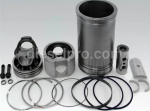
Pistons, Connecting Rods, and Bearings For Detroit Diesel Series 60 (11.1L, 12.7L, 14L)
The pistons, nnecting rods, and bearings are integral to the power transfer system of the Detroit Diesel Series 60 engine. These components translate the energy from combustion into mechanical motion, driving the crankshaft and ultimately powering the vehicle or machinery. Their condition directly affects engine performance, fuel efficiency, and operational longevity. Proper inspection, maintenance, and replacement are essential to ensuring the reliability of these parts.
Inspection Procedures
Thorough inspection of the pistons, connecting rods, and bearings during engine maintenance or overhaul can prevent costly damage and ensure optimal engine performance.
Pistons
- Surface Inspection:
- Examine pistons for scoring, which appears as scratches or grooves caused by debris or insufficient lubrication.
- Check for cracks, particularly around the piston skirt and pin boss areas, which can compromise the piston’s structural integrity.
- Inspect for deformation, such as collapsed skirts or damaged crowns, which may result from overheating or detonation.
- Ring Grooves:
- Inspect the grooves for excessive wear that could reduce the effectiveness of the piston rings.
- Remove any carbon buildup in the grooves to prevent improper seating of the rings.
- Piston Crown:
- Look for pitting, erosion, or burn marks caused by improper combustion or injector spray patterns.
- Ensure the crown is free of significant damage that could affect combustion dynamics.
- Piston Pin and Bore:
- Check for looseness or excessive wear in the pin and bore area, which may indicate improper lubrication or alignment issues.
Connecting Rods
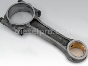
- Visual Inspection:
- Inspect for bending or twisting by comparing the rod’s alignment to a straightedge or using a dedicated tool.
- Check for cracks near the small or big ends, particularly in high-stress areas.
- Small-End Bushing:
- Inspect the small-end bushing for wear or scoring that could indicate improper pin fitment or lubrication issues.
- Replace bushings if the internal diameter exceeds manufacturer tolerances.
- Big-End Bearings:
- Check the bearing surface for discoloration caused by overheating or stress.
- Inspect for uneven wear, which may point to alignment or lubrication problems.
Bearings
- Plastigage Measurement:
- Use plastigage to measure clearance between the bearing and crankshaft journal. Ensure it falls within the allowable range.
- Record measurements and compare them against specifications for connecting rod and main bearings.
- Surface Wear:
- Look for scoring, spalling, or pitting on the bearing surface, as these indicate advanced wear or contamination.
- Check for uneven wear patterns that suggest misalignment or improper lubrication.
- Discoloration:
- Inspect for blueing or other discoloration, which may indicate overheating or oil starvation.
Replacement Guidelines
When inspection reveals damage or wear beyond acceptable limits, replacement of pistons, connecting rods, or bearings is necessary to restore engine functionality and reliability.
Pistons
- Replacement Criteria:
- Replace pistons with cracks, excessive wear, or visible deformation.
- Pistons showing out-of-spec tolerances for diameter, skirt clearance, or weight must be replaced.
- Matching Specifications:
- Ensure new pistons match the weight, dimensions, and material composition of the originals to maintain engine balance and efficiency.
- Ensure new pistons match the weight, dimensions, and material composition of the originals to maintain engine balance and efficiency.
- Piston Rings:
- Always replace piston rings when installing new pistons. Ensure the rings are correctly sized and seated to prevent blow-by and oil consumption.
Connecting Rods
- Replacement Criteria:
- Replace rods showing visible cracks, bending, or twisting, as these can compromise engine alignment and operation.
- Install new small-end bushings if wear or looseness is detected.
- Balancing:
- Match replacement rods for weight to ensure proper crankshaft balancing and prevent vibration.
- Match replacement rods for weight to ensure proper crankshaft balancing and prevent vibration.
- Fasteners:
- Replace connecting rod bolts and nuts as they may stretch during operation and lose their clamping force.
Bearings
- Replacement Guidelines:
- Replace bearings with scoring, excessive wear, or out-of-spec clearances.
- Install new bearings whenever the crankshaft is reconditioned to ensure proper mating surfaces.
- Crankshaft Preparation:
- Polish or regrind crankshaft journals before installing new bearings to remove imperfections and provide a smooth surface.
- Check journal dimensions to confirm they meet tolerances.
Tolerances and Wear Limits
Adhering to manufacturer-specified tolerances is essential for the long-term performance of pistons, connecting rods, and bearings.
Piston Ring Clearance
- End Gap:
- Measure the piston ring end gap using feeler gauges.
- Typical specifications: 0.25–0.38 mm (0.010–0.015 in.).
- Side Clearance:
- Check side clearance between the ring and the groove. Replace rings or pistons if clearance exceeds allowable limits.
Connecting Rod Bearings
- Plastigage Measurement:
- Apply plastigage to the journal and tighten the bearing cap to torque specifications.
- Acceptable clearance: 0.025–0.076 mm (0.001–0.003 in.).
- Out-of-Spec Bearings:
- Replace bearings if clearance exceeds the maximum specified range.
Crankshaft Journals
- Inspection for Wear:
- Use a micrometer to measure journal diameters. Compare readings against factory specifications.
- Replace or regrind journals with wear exceeding 0.002–0.005 in..
- Out-of-Round Conditions:
- Measure journals at multiple points to identify ovality. Replace or machine journals as needed.
Reassembly Tips
Proper reassembly of pistons, connecting rods, and bearings is critical to ensure the engine operates efficiently and reliably.
Ensure Cleanliness
- Debris-Free Assembly:
- Thoroughly clean all components to remove dirt, oil residue, and metal shavings.
- Blow out oil passages with compressed air to ensure unobstructed lubrication.
- Surface Preparation:
- Inspect sealing surfaces and threads for damage. Repair as necessary before assembly.
Follow Torque Specifications
- Precise Torque Application:
- Use a calibrated torque wrench to tighten fasteners to exact specifications.
- Torque connecting rod bolts evenly in multiple stages to prevent distortion.
- Final Tightening:
- Verify torque values and recheck after initial operation if required by the manufacturer.
Lubricate All Moving Parts
- Assembly Lubricant:
- Apply clean engine oil or assembly lube to pistons, rings, journals, and bearings to reduce friction during start-up.
- Apply clean engine oil or assembly lube to pistons, rings, journals, and bearings to reduce friction during start-up.
- Piston Installation:
- Use a ring compressor to install pistons without damaging the rings or cylinder walls.
Stagger Piston Rings
- Ring Gap Positioning:
- Offset piston ring gaps to prevent blow-by and improve compression.
- Ensure no two ring gaps align with each other or the piston pin.
Final Testing
After reassembly, perform these checks to ensure all components function properly.
Manual Crankshaft Rotation
- Smooth Movement:
- Rotate the crankshaft manually to ensure all components move without binding or resistance.
- Rotate the crankshaft manually to ensure all components move without binding or resistance.
- Noise Inspection:
- Listen for grinding or unusual noises that may indicate misalignment or insufficient clearance.
Oil and Coolant System Checks
- Refill Systems:
- Fill the engine with clean oil and coolant.
- Inspect for leaks around seals, gaskets, and connections.
- System Integrity:
- Check oil pressure and coolant levels during engine start-up to ensure proper circulation.
Start-Up and Monitoring
- Initial Operation:
- Start the engine and monitor for vibrations, unusual noises, or temperature fluctuations.
- Start the engine and monitor for vibrations, unusual noises, or temperature fluctuations.
- Final Inspection:
- Shut down the engine after a brief warm-up period and inspect all components for proper alignment, timing marks, and seal integrity.
Conclusion
This detailed overview of engine components and overhaul procedures ensures accurate and efficient servicing of Detroit Diesel Series 60 engines. By following these guidelines, technicians can maintain engine reliability and extend its operational life.
Parts Catalog for 11.1L Detroit Diesel 60 Series Marine Engine
Parts Catalog for 12.7L Detroit Diesel 60 Series Marine Engine
Parts Catalog for 14L Detroit Diesel 60 Series Marine Engine