Cylinder Block and Liner System
The cylinder block forms the engine’s foundation, housing crucial components such as pistons, liners, and the crankshaft. It is designed to withstand immense forces while maintaining precise alignment for moving parts.
Parts Catalog for 11.1L Detroit Diesel 60 Series Marine Engine
Parts Catalog for 12.7L Detroit Diesel 60 Series Marine Engine
Parts Catalog for 14L Detroit Diesel 60 Series Marine Engine
Functions of the Cylinder Block and Liner:
- Structural Support: Provides rigidity and alignment for engine components.
- Heat Dissipation: Transfers heat generated during combustion to the cooling system.
- Compression Chamber Formation: Works with liners to seal the combustion chamber.
Techniques for Inspecting and Replacing Liners:
- Inspection:
- Remove the cylinder head to access the liners.
- Check for scoring, pitting, or wear on liner surfaces.
- Measure the liner bore diameter using a bore gauge to confirm specifications.
- Replacement Steps:
- Use a hydraulic puller to remove worn liners.
- Clean the block thoroughly to remove debris from the liner seat.
- Apply an appropriate sealant to prevent coolant leaks during installation.
- Press-fit new liners using a suitable tool, ensuring proper alignment.
- Verify liner protrusion above the deck to meet specifications for sealing.
Pro Tip: Always inspect the block for cracks or damage during liner replacement to prevent recurring issues.
Cylinder Head and Valve Mechanisms
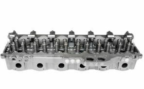
The cylinder head seals the combustion chamber and supports intake, exhaust valves, and injectors. Its role is pivotal in ensuring efficient airflow and combustion.
Maintenance of the Cylinder Head and Its Components:
- Inspection: Check for cracks or warping using dye-penetrant testing and a straightedge.
- Cleaning: Remove carbon deposits from valve seats and combustion chambers.
- Valve Servicing: Inspect valve faces, guides, and springs for wear and replace as necessary.
Adjusting Valve Lash and Injector Height:
- Valve Lash Adjustment:
- Set the engine to top dead center (TDC) for the cylinder being adjusted.
- Use a feeler gauge to measure and adjust clearance between the rocker arm and valve stem.
- Tighten to the specified torque while holding the adjustment screw.
- Injector Height Adjustment:
- Align the timing mark on the crankshaft for the specific injector.
- Use the height gauge to measure the injector’s plunger position.
- Adjust the screw to achieve proper height for optimal fuel injection.
Crankshaft and Gear Train
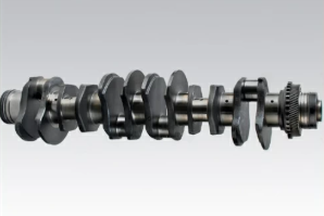
The crankshaft transforms linear piston motion into rotational energy, driving auxiliary systems through the gear train.
Proper Handling of the Crankshaft and Bearings:
- Inspection:
- Remove the crankshaft and clean thoroughly.
- Check for scoring, cracks, and journal wear using micrometers.
- Measure bearing clearances with plastigauge to ensure proper oil film thickness.
- Reinstallation:
- Lubricate bearings with engine oil to prevent dry starts.
- Torque main bearing caps to specifications, using a cross-pattern sequence.
Gear Train Timing and Noise Troubleshooting:
- Timing: Align timing marks on the crankshaft, camshaft, and intermediate gears to ensure proper synchronization of valve and injector operation.
- Noise Troubleshooting:
- Inspect gear lash with a dial indicator to confirm proper clearance.
- Replace chipped or worn gears to prevent whining or rattling noises.
Pro Tip: Regularly inspect gear train lash during maintenance to avoid timing discrepancies and excessive wear.
Pistons and Connecting Rods
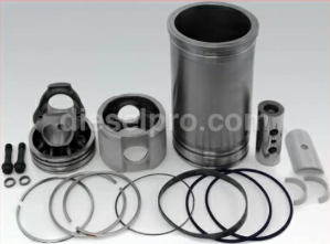
Pistons transfer combustion force to the crankshaft through connecting rods, requiring precision during installation to maintain balance and functionality.
Step-by-Step Guide for Piston Replacement:
- Removal:
- Remove the cylinder head and oil pan for access.
- Disconnect the connecting rod from the crankshaft.
- Use a piston ring compressor to slide the piston and rod assembly out.
- Inspection:
- Examine pistons for scuffing, cracks, or excessive wear.
- Measure piston diameter and skirt clearance with micrometers.
- Installation:
- Install new piston rings using a ring expander, ensuring correct orientation.
- Apply engine oil to the rings and piston skirt for lubrication.
- Use a ring compressor to insert the piston into the cylinder, aligning the rod with the crankshaft.
- Torque connecting rod caps to specifications using the proper sequence.
Connecting Rod Inspection and Assembly:
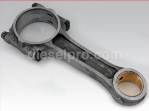
- Inspection:
- Check rods for bending or twisting using specialized jigs.
- Measure the small- and big-end bore diameters for wear.
- Assembly:
- Install bushings and torque bolts to specifications.
- Ensure the rod and cap are paired correctly to maintain original balance.
Pro Tip: Replace rod bolts when reassembling to avoid potential fatigue failure.
Camshaft and Timing
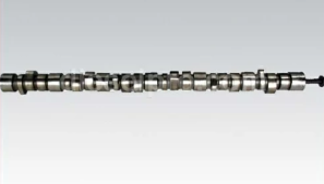
The camshaft operates valves and injectors by converting rotational motion into linear motion via lobes.
Aligning the Camshaft and Timing Gears:
- Pre-alignment Steps:
- Position the crankshaft at TDC for cylinder one.
- Align the camshaft timing mark with the crankshaft timing mark.
- Gear Installation:
- Install the timing gears, ensuring proper mesh with marked teeth.
- Torque bolts to specifications, following the sequence outlined in the manual.
Troubleshooting Timing-Related Issues:
- Symptoms of Incorrect Timing:
- Difficulty starting, rough idling, or reduced power.
- Backfiring or unusual valve train noises.
- Diagnosis:
- Verify alignment of timing marks on all gears.
- Measure camshaft end play and gear lash to ensure they are within limits.
- Inspect timing gears for wear, cracks, or missing teeth.
Pro Tip: After timing adjustments, rotate the crankshaft manually to confirm no interference before engine startup.
By following these detailed procedures, technicians can ensure optimal performance and reliability of Detroit Diesel Series 60 engines. This thorough understanding of each system and component will minimize downtime and maintain engine longevity.
Parts Catalog for 11.1L Detroit Diesel 60 Series Marine Engine
Parts Catalog for 12.7L Detroit Diesel 60 Series Marine Engine
Parts Catalog for 14L Detroit Diesel 60 Series Marine Engine


 Free US Calls: 1-888-433-4735
 International: 305-545-5588