

 Free US Calls: 1-888-433-4735
 International: 305-545-5588
After successfully completing reassembly of the Twin Disc MG520 Marine Gear, the last and equally important step is final installation and comprehensive testing. This phase ensures your gear is correctly aligned, fully connected, and performs reliably under both dockside and at-sea conditions.
Whether you’re installing a freshly rebuilt MG520 on a commercial tug, a fishing vessel, or a high-performance workboat, attention to detail during alignment, torqueing, and functional testing is essential for long-term reliability.
This guide covers alignment, hydraulic/electrical reconnection, and a detailed testing protocol, including initial startup checks and a full sea trial checklist. By following these steps carefully, you’ll protect your investment and guarantee smooth, powerful performance from the MG520.
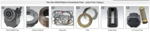
Parts Catalog for Twin Disc MG520 Marine Transmissions
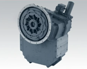
Rebuilt Twin Disc MG520 Marine Transmissions
Plate Kit For Twin Disc MG520 Marine Transmission
Gasket Kits For Twin Disc MG520 Marine Transmission
Aligning Transmission with Engine For Twin Disc MG520 Marine Gear
Alignment is critical. Improper alignment between the engine flywheel and the MG520 input shaft is a common cause of:
- Premature input bearing failure
- Clutch dragging or misengagement
- Vibration in the driveline
- Excessive heat in the pilot bushing
- Noise and gear wear
1. Alignment Tools and Techniques
Proper alignment requires precision tools and a structured procedure. You are aiming to align both the angular and parallel offset between the gear input flange and the engine flywheel housing.
Required Tools:
- Dial Indicator Kit with Magnetic Base
- Straightedge and Feeler Gauges
- Engine hoist or lifting jack for micro-adjustments
- Laser alignment tools (optional but ideal for critical jobs)
Alignment Procedure (Standard Dial Indicator Method):
- Mount the Transmission to the Engine Temporarily
- Use alignment dowels and hand-snug bolts—do not torque yet.
- Use alignment dowels and hand-snug bolts—do not torque yet.
- Measure Radial Runout
- Attach a magnetic base to the gear input flange.
- Rotate the crankshaft by hand.
- The dial indicator should read less than 0.003″ total indicated runout.
- Adjust the transmission angle if needed with shims or adjustable mounts.
- Measure Face Runout (Axial)
- Flip the dial to measure the distance to the flywheel face.
- Rotate and note variation. Total face runout should also be under 0.003″.
- Laser Alignment Option
- Position the laser tool on the engine coupling.
- Adjust until laser is centered in the target crosshairs on the transmission flange.
- Correct Misalignment
- Use shims, jack bolts, or engine mount adjustments.
- Align until both radial and axial runout values are within spec.
- Final Bolt Snug
- Once aligned, fully torque the mounting bolts in crisscross sequence.
- Once aligned, fully torque the mounting bolts in crisscross sequence.
2. Mounting Bolt Torque Guidelines
Each mounting bolt must be torqued evenly to avoid distorting the transmission housing or warping the bellhousing face.
| Bolt Size | Suggested Torque (Grade 8 bolts) |
| 3/8″-16 | 33-45 ft-lbs |
| 7/16″-14 | 55-70 ft-lbs |
| 1/2″-13 | 75-105 ft-lbs |
| 5/8″-11 | 165-210 ft-lbs |
⚠️ These are general torque values. Always verify against Twin Disc MG520 OEM specs.
Hydraulic and Electrical Connections For Twin Disc MG520 Marine Gears
Once the transmission is aligned and mounted, reconnect all hydraulic hoses, cooling lines, and—if applicable—EC300 control wiring.
1. Reconnecting Hydraulic Hoses
The MG520 relies on hydraulic pressure to actuate its clutch pack. Failing to reconnect this system correctly will result in shifting issues, gear slippage, and pressure loss.
Checklist:
- Reconnect high-pressure supply lines to the clutch valve block.
- Attach return lines to the lube oil reservoir or cooler circuit.
- Inspect and replace O-rings or copper washers at banjo fittings or threaded ports.
- Confirm hoses are routed away from hot surfaces or sharp edges.
- Torque hydraulic fittings using two wrenches—one to hold, one to tighten.
2. Reconnecting the Oil Cooler
The oil cooler is typically mounted remotely and helps prevent thermal breakdown of the transmission fluid.
Best Practices:
- Ensure proper orientation of cooler lines (inlet and outlet).
- Replace any worn clamps, hoses, or corroded fittings.
- Torque fittings to avoid overtightening, which may crack aluminum cooler ports.
- Once connected, pressure test the cooler loop to ensure no leaks.
3. EC300 Electrical Wiring (If Applicable)
The Twin Disc EC300 system integrates electronic throttle and transmission control. After rebuild, all wiring must be reconnected exactly as removed.
Checklist:
- Reconnect control head cables to the transmission-mounted ECU.
- Secure all connectors with locking tabs or waterproof boots.
- Verify that ground straps and power leads are connected.
- Tie up wiring using marine-grade zip ties to prevent movement.
- Use dielectric grease on electrical pins if exposed to saltwater environments.
✅ Pro Tip: After powering up, use the EC300 self-diagnostic mode to ensure communication between control head and transmission ECU is active.
4. Bleeding the Hydraulic System
Before startup, the hydraulic circuit must be bled to remove air. Air bubbles can cause:
- Shifting delays
- Low clutch pressure
- Gear chatter
Bleeding Procedure:
- Fill the Transmission with Proper Oil
- SAE 30W or 40W non-detergent oil as recommended
- Fill to dipstick level
- Loosen the Return Line Fitting
- Allow trapped air to escape as fluid backfills the system
- Allow trapped air to escape as fluid backfills the system
- Manually Rotate the Input Shaft
- Helps move oil into all galleries
- Helps move oil into all galleries
- Shift Through Gears at Idle
- Once powered up, shift forward, neutral, and reverse
- Hold each gear for 5 seconds to allow clutch circuits to pressurize
- Recheck Fluid Level
- Top off oil as needed after bleeding is complete
- Top off oil as needed after bleeding is complete
Functional Testing For Twin Disc MG520 Marine Gear
With all systems connected, you’re ready to start the engine and test the gear under controlled conditions. This step is vital before sea trials and ensures all repairs were successful.
1. Initial Startup and Warm-Up Checks
Before You Start:
- Confirm:
- Transmission oil is at correct level
- All bolts and flanges are torqued
- No tools or rags are left in the bilge or near couplings
- Fire extinguisher is nearby
Startup Steps:
- Start Engine and Idle at 600–800 RPM
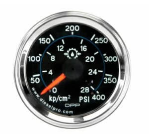
- Observe Oil Pressure
- Attach a hydraulic gauge to the forward and reverse clutch ports
- Normal pressure is 250–400 PSI during engagement
- Inspect for Leaks
- Look around:
- Input and output seals
- Cooler lines
- Hydraulic block
- Inspection covers
- Look around:
- Shift into Forward and Reverse
- Do this while vessel is secured at dock
- Engagement should be:
- Smooth
- Quick (within 2 seconds)
- Without excessive noise or vibration
- Do this while vessel is secured at dock
Monitor During Warm-Up:
- Transmission Oil Temp should rise gradually to 140–180°F
- No foaming in sight glass
- No spike in pressure readings
⚠️ If pressure spikes or drops dramatically, shut down immediately and re-inspect.
2. Monitoring Pressure, Temperature, and Engagement
Key Gauges to Watch:
| Metric | Normal Range |
| Forward Clutch Pressure | 250–400 PSI |
| Reverse Clutch Pressure | 250–400 PSI |
| Lube Oil Pressure | 20–60 PSI |
| Transmission Oil Temp | 140–180°F |
Install temporary mechanical gauges if vessel does not have a full monitoring system.
Signs of Trouble:
- Slow Engagement: May indicate air in the system or worn clutches.
- Pressure Drop at Shift: Leaks in control valve or damaged seals.
- Grinding or Clunking: Misalignment, low oil, or warped plates.
- Overheating: Oil cooler issues, fluid breakdown, or slipping clutch.
3. Sea Trial Checklist
After dockside testing, perform a controlled sea trial to confirm full system performance under load.
Pre-Departure Checklist:
- All bolts and connections rechecked
- Oil topped off
- Fire suppression systems active
- Backup radio/communication ready
- Technician and observer on board
- All tools secured
During Sea Trial:
- Idle Out of Harbor
- Shift into gear and check for vibration or delay
- Shift into gear and check for vibration or delay
- Accelerate to Cruise RPM
- Monitor engagement at higher torque
- Monitor engagement at higher torque
- Reverse Test
- Shift into reverse from idle; should engage smoothly
- Shift into reverse from idle; should engage smoothly
- Sharp Turns and Maneuvers
- Observe gear performance under load and angle
- Observe gear performance under load and angle
- Full Throttle Burst
- Check for slipping or pressure loss at high RPM
- Check for slipping or pressure loss at high RPM
- Monitor Gauges Continuously
- Note any deviation in pressure or temp
- Note any deviation in pressure or temp
Post-Trial Inspection:
- Recheck all bolts and flanges for signs of movement
- Inspect for fresh oil leaks
- Re-verify fluid level and color
- Clean out bilge of any residue from test
✅ Tip: Create a logbook entry for transmission hours, pressure readings, and notes for future reference.
Conclusion: Testing Is the Final Proof of a Job Well Done For Twin Disc MG520 Marine Gear
Final installation and testing of the MG520 isn’t just about confirming the rebuild worked—it’s your first line of defense against future failure. From precision alignment to hydraulic system bleeding, from torqueing flanges to performing a thorough sea trial, every detail matters.
A successful install isn’t measured by how fast the job is done—but by how reliably that marine gear performs on open water, in tight harbors, and under heavy load.
Diesel Pro Power supports you with premium rebuild kits, seal sets, valve components, and more to keep your Twin Disc MG520 operating at its best.
Rebuilt Twin Disc MG520 Marine Transmissions
Plate Kit For Twin Disc MG520 Marine Transmission
Gasket Kits For Twin Disc MG520 Marine Transmission
Videos About Twin Disc Transmissions
6 Reasons Your Twin Disc Transmission Has Low Oil Pressure
7 Reasons Your Twin Disc Transmission Is Overheating
3 Reasons Your Clutch Plates in Your Twin Disc Transmission Are Making Excessive Noise
Bull Gear On A Twin Disc Transmission
Rebuilt Twin Disc Transmissions