

 Free US Calls: 1-888-433-4735
 International: 305-545-5588
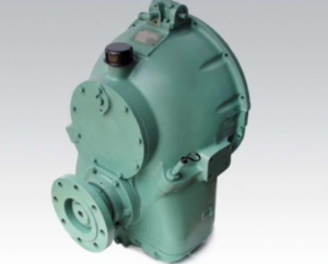
Allison M Rebuilt Marine Transmission
Overhaul Kit & Related Components For Allison M
Allison M Seals
Allison M Clutch Plates
Allison M Hydraulic Pump
Allison M Selector Valve & Related Components
Allison M Bearings & Related Components
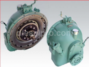
Allison MH Rebuilt Transmission
Allison MH Overhaul Kit & Related Components
Allison MH Seals
Allison MH Clutch Plates & Related Components
Allison MH Hydraulic Pump
Allison MH Selector Valve
Allison MH Bearings & Related Components
Overview of the Hydraulic Control System
The hydraulic control system is the central nervous system of the Allison M & MH series marine transmissions. Without it, shifting gears, engaging clutches, and maintaining lubrication would be impossible. Unlike some mechanical transmissions, Allison marine transmissions rely entirely on oil pressure generated and routed through this system to perform critical functions such as clutch application, internal lubrication, cooling, and gear engagement.
At its core, the system is composed of a gear-driven oil pump, selector valve, solenoids (in some later models), an oil strainer, full-flow oil filter, oil cooler, internal oil passages, and pressure regulation components. Each part is precision-machined and designed to withstand continuous operation in demanding marine environments—both commercial and recreational.
The system performs the following essential roles:
- Generates pressure required to apply forward and reverse clutches.
- Maintains constant lubrication of rotating components.
- Cools internal components to prevent overheating.
- Directs and controls oil flow through various circuits.
It’s important to note that hydraulic pressure must remain consistent and within factory specifications to prevent premature wear or failure. Even small deviations in pressure or flow can manifest in delayed shifts, overheating, or total loss of propulsion.
Valve Body Components and Layout
The valve body in the Allison M & MH series marine transmission is the brain of the hydraulic control system. It houses the selector valve, detent mechanism, control passages, and ports that direct oil to either the forward or reverse clutch pack. Let’s examine the layout and functions of these elements:
Selector Valve Assembly:
- Operated by a manual shift lever via linkage.
- Allows the operator to choose between forward, neutral, and reverse.
- Moves a spool-type valve inside the valve body, aligning ports to route pressurized oil to the appropriate clutch.
- Provides mechanical detents for tactile feedback, ensuring secure gear selection.
Internal Passages:
- Precisely machined in the valve body casting.
- Direct oil flow from the pump to the filter, cooler, and into the clutches.
- Engineered for minimal restriction and optimal flow rates.
Pressure Regulation Port:
- Located within or adjacent to the oil pump housing.
- Prevents excessive hydraulic pressure that could damage clutches or seals.
- Some models feature external ports for easier pressure gauge access during diagnostics.
Auxiliary Check Valves and Dump Valves:
- Integrated into the valve body or flywheel.
- Ensure pressure is relieved or redirected under certain conditions, such as transitioning from forward to neutral.
- Help prevent clutch drag or overlap, which can cause excessive heat and friction.
Pressure Testing Procedures
Routine pressure testing is essential for diagnosing performance issues and ensuring the transmission is operating within specifications. The goal is to confirm that the forward and reverse clutch circuits are receiving the correct hydraulic pressure under load and at idle.
Required Tools:
- Calibrated hydraulic pressure gauge (range: 0–200 psi).
- Threaded pressure port adapter.
- Transmission service manual for model-specific test port location and pressure specs.
Test Setup:
- Warm up the engine and transmission to normal operating temperature (180–200°F or 83–93°C).
- Locate the test port near the selector valve or main hydraulic circuit.
- Thread the pressure gauge into the port securely.
- With the engine at idle (typically 600–800 rpm), record the pressure in neutral.
- Engage forward gear and increase engine rpm to 1800. Record pressure.
- Repeat in reverse at 1500 rpm.
- Compare results to factory specs:
- Forward: 130 psi minimum at 1800 rpm
- Reverse: 110 psi minimum at 1500 rpmM MH Series
Interpreting Results:
- Low pressure may indicate a worn pump, clogged filter, leaking gasket, or internal leak in clutch seals.
- High pressure can point to a malfunctioning regulator valve or blocked return circuit.
- Fluctuating pressure might be caused by air in the hydraulic system or an intermittent obstruction.
Pressure testing should be performed after every oil change, major service, or suspected hydraulic issue.
Solenoid Function and Replacement
While early M and MH series models use fully mechanical selector valves, some late-model MH transmissions introduced electric solenoids to control or assist valve movement. These solenoids operate under 12V DC and are controlled by engine or transmission management systems.
Function of Solenoids:
- Convert electrical signals into mechanical movement.
- Shift internal spool valves to engage specific circuits.
- Reduce the need for manual shift levers in some control configurations.
- Improve response time in modernized systems.
Symptoms of Faulty Solenoids:
- Delayed gear engagement.
- Transmission stuck in neutral or reverse.
- Inconsistent operation or failure to shift under load.
- Diagnostic fault codes (if connected to ECM).
Replacement Procedure:
- Disconnect the battery and secure all wiring.
- Access the valve body or control housing.
- Disconnect the electrical harness from the solenoid(s).
- Remove retaining screws or bolts securing the solenoid.
- Gently extract the solenoid without damaging seals or passages.
- Lubricate new solenoid O-rings with clean transmission oil.
- Install the new solenoid, tighten fasteners to spec, and reconnect wiring.
- Test system operation manually and under power.
Always ensure you use a solenoid rated for your specific transmission model and verify voltage compatibility.
Internal Passage Cleaning
Over time, contamination such as sludge, varnish, or metallic debris can accumulate in the internal hydraulic passages, restricting oil flow and causing performance loss.
When to Clean Passages:
- After a catastrophic clutch failure.
- Following oil contamination (e.g., water ingress or coolant leakage).
- During a complete overhaul or rebuild.
- If pressure testing reveals intermittent or unexplained drops.
Cleaning Steps:
- Drain all fluid from the transmission.
- Remove the valve body and selector assembly.
- Use a dedicated solvent-based flushing solution—do not use gasoline or brake cleaner.
- Use compressed air with a regulated nozzle (below 50 psi) to force solvent through internal passages.
- Inspect for blockages, burrs, or corrosion.
- Use pipe cleaners or soft-bristled brushes for stubborn areas.
- Reassemble using new gaskets and torque to specifications.
Important Tips:
- Never scrape or drill passage surfaces.
- Use lint-free wipes and avoid contaminating new oil with residues.
- Replace all filters and inspect the cooler before restarting the engine.
Testing With Hydraulic Gauges
Hydraulic gauges provide real-time insight into system health. Aside from pressure tests, gauges can also be used to monitor temperature and detect internal leakage.
Recommended Gauges:
- Analog pressure gauge (0–200 psi)
- Digital infrared thermometer (non-contact)
- Temperature gauge with surface probe
- Flow meter (optional for advanced testing)
What to Monitor:
- Idle pressure: Should be stable without significant drop.
- Pressure under load: Confirms clutch engagement integrity.
- Backpressure: May indicate restrictions or internal valve sticking.
- Temperature rise: Excessive heat can signal internal friction or blocked cooling flow.
Testing Intervals:
- During initial startup after overhaul.
- Every 500 operating hours for commercial vessels.
- After unusual noise, delayed shifting, or pressure alarms.
Data Logging:
In commercial fleets, it is beneficial to log hydraulic pressure and temperature readings during routine inspections. Establishing a baseline can help detect wear trends and catch issues before failure occurs.
System Upgrades and Preventative Improvements
For vessels operating under high load, extreme climates, or extended intervals between servicing, upgrading the hydraulic system can increase reliability.
Available Enhancements:
- High-capacity oil coolers for better thermal management.
- Inline magnetic filters to capture micro-particles.
- Bypass filtration systems for continuous cleaning.
- Pressure relief upgrades with adjustable settings.
- Temperature alarms for early detection of overheating.
Best Practices:
- Always use the correct type and grade of engine oil as transmission fluid.
- Inspect oil strainers at every oil change.
- Replace filters with OEM-equivalent or better-quality aftermarket elements.
- Clean the breather regularly to prevent internal pressure buildup.
Common Hydraulic Failures and Troubleshooting
Issue: Delayed engagement in forward or reverse
- Possible causes: Low pressure, worn clutches, air in system, faulty selector valve.
Issue: Overheating
- Possible causes: Blocked cooler, low oil level, clutch slippage, high backpressure.
Issue: Fluctuating oil pressure
- Possible causes: Dirty filter, worn pump gears, regulator valve malfunction.
Issue: No clutch engagement
- Possible causes: Valve body failure, zero hydraulic pressure, solenoid fault.
Issue: Oil leaks
- Possible causes: Cracked housing, failed gaskets, loose fittings, or overpressure.
Conclusion
The hydraulic control system of the Allison M & MH marine transmissions is fundamental to their performance, durability, and safe operation. Whether in a pleasure yacht or a high-duty commercial vessel, the integrity of the hydraulic system directly impacts maneuverability, propulsion, and reliability. By understanding the system’s components, maintaining pressure standards, and performing regular testing and servicing, operators can prevent costly failures and ensure long-term operational success.
For more technical information including exploded diagrams, flow schematics, and advanced troubleshooting procedures, refer to the original Allison service manual or contact a professional marine transmission specialist.
Allison M Rebuilt Marine Transmission
Overhaul Kit & Related Components For Allison M
Allison M Seals
Allison M Clutch Plates
Allison M Hydraulic Pump
Allison M Selector Valve & Related Components
Allison M Bearings & Related Components
Allison MH Rebuilt Transmission
Allison MH Overhaul Kit & Related Components
Allison MH Seals
Allison MH Clutch Plates & Related Components
Allison MH Hydraulic Pump
Allison MH Selector Valve
Allison MH Bearings & Related Components