

 Free US Calls: 1-888-433-4735
 International: 305-545-5588
The Twin Disc MG5114A marine transmission operates using a closed hydraulic system—a precise network of fluid passages, pumps, actuators, and valves that make reliable gear engagement possible under load. This system is the nervous system of your gear: without healthy hydraulic flow and pressure regulation, even a mechanically sound transmission will fail to operate properly.
Whether you’re troubleshooting gear engagement issues, diagnosing pump failure, or servicing the control valve assembly during an overhaul, this guide will provide a comprehensive, practical overview of how the MG5114A hydraulic control system works, how to maintain it, and how to restore it when things go wrong.
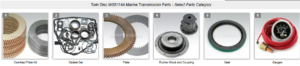
Parts Catalog for Twin Disc MG5114A Marine Transmissions
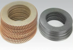
Plate Kit For Twin Disc MG5114A Marine Transmission
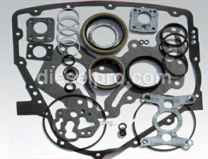
Gasket Kits For Twin Disc MG5114A Marine Transmission
Control Valve and Actuator Functions
Understanding the Hydraulic Shift Logic
The MG5114A uses hydraulic clutch packs to switch between Forward (F), Neutral (N), and Reverse (R). These shifts occur through oil flow regulation, not mechanical linkages (although external linkages or solenoids can trigger the shift).
At the heart of this system is the control valve body. When you shift the helm lever or electronic controller:
- A signal is sent (mechanical or electric) to the control valve
- The valve routes pressurized oil to the appropriate clutch pack
- The forward clutch engages, or
- The reverse clutch engages, or
- Both are de-pressurized (neutral)
This all happens in a split second, with hydraulic pressure ranging from 150–300 PSI acting on pistons to clamp the clutch discs.
Components in the Valve System:
- Spool valves – Slide internally to route flow
- Spring detents or centering springs – Return valve to neutral
- Solenoids (if applicable) – Actuate the valve electronically
- Check valves – Prevent reverse flow
- Manual override arms – Allow hand control in emergencies
- Pressure relief valve – Protects system from over-pressure events
Key Insight: If your transmission doesn’t engage forward or reverse—or engages both simultaneously—it’s almost always related to the control valve, oil pressure, or electrical shift signal.
Troubleshooting Valve Body Issues
Before removing the valve body, always perform the following checks:
- Check Oil Pressure:
- Use a 0–500 PSI gauge at the test port
- Verify pressure in Neutral, Forward, and Reverse
- Low pressure = pump, blockage, or valve failure
- Inspect External Linkages or Solenoids:
- Is the shift cable moving the control arm fully?
- Are solenoids getting 12V power and clicking on engagement?
- Any delay in signal may be electrical—not hydraulic
- Oil Condition:
- Burnt or dirty oil can clog valve passages
- Milky fluid may reduce seal effectiveness and create slippage
- Debris can lodge inside the spool valve and block movement
Common Valve Body Symptoms:
| Symptom | Likely Cause |
| No gear engagement | Valve stuck in neutral, solenoid failure |
| Harsh or delayed shift | Clogged valve, low pressure, damaged spool |
| Stuck in gear | Return spring failure or spool seizure |
| Clutch pack dragging in neutral | Valve not fully returning or misrouted pressure |
Diagnostic Tip: Many technicians misdiagnose slipping as clutch wear, when it’s actually the result of improper pressure routing inside the valve body.
Oil Pump Functionality
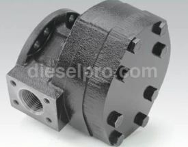
The MG5114A relies on a dedicated oil pump to circulate transmission fluid and provide the hydraulic pressure necessary for clutch engagement. Without a functioning pump, your gear will neither shift nor lubricate itself—and catastrophic failure is just minutes away.
Gear or Vane-Type Pump Explanation
While exact configurations vary slightly by model and year, the MG5114A generally uses a gear-type pump, driven off the input shaft.
Gear Pump Characteristics:
- Two precision-meshed gears inside a close-clearance housing
- As they rotate, oil is drawn in and forced through the pump body
- Known for simplicity and durability
- Can generate 250+ PSI under load
Some variants or specialized models may use a vane-type pump, which operates with sliding vanes within a rotor and maintains better flow at lower speeds. However, most MG5114As are gear-pump-equipped.
Functions of the Oil Pump:
- Delivers pressure to clutch pistons
- Lubricates all internal gears and bearings
- Circulates oil through external coolers and filters
- Provides pressure for shift actuation and engagement
Important Note: The pump only turns when the engine is spinning. That’s why you always check transmission pressure with the engine running.
Symptoms of a Failing Pump
Oil pump failures are rare but serious, often occurring due to contamination, starvation, or extended abuse. These are the classic warning signs:
1. Low or No Oil Pressure
- Pressure readings below 150 PSI
- Pressure that fluctuates erratically
- No clutch engagement despite shift command
2. Transmission Overheating
- If the oil isn’t circulating, the unit can overheat within minutes
- Scorched oil, warped clutch discs, and failed seals follow
3. No Oil at Cooler Return
- Disconnect the oil return line briefly (use care)
- No flow = pump not circulating
4. Noise from the Pump
- Grinding or whining at idle
- Sudden changes in noise after startup
5. Metallic Debris in Oil
- Pump gears or housing may be disintegrating internally
Servicing the Valve Body
If you’re confident the issue lies in the valve body—and not just pressure loss or signal error—you can remove and rebuild it. This is a precision task that must be done in a clean, organized, and contamination-free environment.
Disassembly Precautions
- Clean exterior thoroughly before opening
- Lay out a clean bench with trays or magnetic organizers
- Photograph or diagram spool and spring orientation
- Remove bolts in a cross-pattern to prevent distortion
- Watch for:
- Ball checks and small springs under pressure
- Preloaded plungers
- Fragile gaskets and valve body shims
What to Inspect:
- Spool valves – Slide them in their bores
- Should be smooth and free-moving
- Clean with solvent and lint-free cloth
- Bores – Check for scoring, varnish, or metal
- Gaskets – Replace with new every time
- Check valves and orifices – Inspect for clogging or distortion
- Relief spring and plug – Test for movement and tension
If you find rust, pitting, or scoring—replace the affected components. Minor damage can restrict flow and cause irregular shifting or slippage.
Cleanliness and Reassembly Tips
The valve body is a precision hydraulic controller. Even a grain of grit or a torn O-ring can wreck performance.
Cleaning Best Practices:
- Use solvent bath or ultrasonic cleaner for small components
- Rinse with compressed air and ensure parts are completely dry
- Never use paper towels—only lint-free rags or lab wipes
- Clean mating surfaces with brake cleaner and plastic scraper (no metal blades)
Reassembly Tips:
- Lubricate spools with fresh hydraulic oil during assembly
- Torque all fasteners to spec and in sequence
- Replace all gaskets, O-rings, and crush washers
- Use assembly lube on detent balls or spring-loaded parts
- Test spool movement after reassembly—should slide freely by hand
Final Checks Before Reinstalling:
- Bench test valve if possible with air or low-pressure fluid
- Ensure no leftover parts, mismatched spools, or inverted springs
- Label ports or mark them clearly to prevent reversed hose installation
Post-Service Function Test
Once the valve body and pump are serviced and the unit is reinstalled:
- Fill with new SAE 30 or SAE 40 oil
- Run the engine in neutral and check pressure at the test port
- Cycle forward and reverse shifts several times
- Monitor for:
- Smooth, rapid engagement
- Consistent pressure with no spikes or dropouts
- Proper neutral disengagement
- Return flow from cooler to confirm pump performance
Caution: Do not sea trial the vessel until oil temp, shift feel, and pressure readings are all within normal range.
Tools and Supplies Checklist
- 0–500 PSI hydraulic test gauge
- Valve body torque specs (OEM manual)
- Lint-free rags and solvent
- Assembly lubricant or ATF
- New gasket and seal kit
- Magnetic parts tray
- Clean bench space
- Thread sealant (non-hardening, hydraulic-grade)
- Flashlight and magnifier
- Compressed air for drying passages
When to Replace the Valve Body or Pump
Sometimes inspection reveals wear too extensive to rebuild. Consider replacing the valve body or oil pump when:
- Spools are frozen or severely scored
- Mating bores have wall damage
- Pressure relief valve fails to regulate
- Pump gears are chipped or housing is grooved
- System fails a pressure test even after cleaning
Diesel Pro Power offers replacement parts and complete rebuilt MG5114A valve bodies for field or workshop installs.
Summary Troubleshooting Table
| Symptom | Suspected Cause | Recommended Fix |
| No gear engagement | Valve stuck or solenoid failed | Inspect spool, solenoid signal |
| Slipping in one gear | Pressure not reaching clutch | Clean and rebuild valve body |
| Harsh engagement or clunking | Valve routing delay | Replace gaskets, check springs |
| Pressure drop at shift point | Worn pump or internal leak | Replace oil pump |
| No cooler return flow | Pump not circulating | Inspect for drive gear failure |
| Whining noise from transmission | Cavitation or worn gears | Replace oil and service pump |
Final Thoughts on MG5114A Hydraulic Control System
The hydraulic system inside the Twin Disc MG5114A is a marvel of precision marine engineering—able to transmit hundreds of horsepower at the flick of a lever. But that performance depends on clean oil, healthy pressure, and a functional control valve.
By inspecting, cleaning, testing, and maintaining your control valve and oil pump, you’re preserving the heart of your marine drivetrain.
- Always follow cleanliness protocols
- Never reuse damaged valves, springs, or seals
- Test pressure regularly—data tells the story
- Rebuild with precision, or replace with trusted aftermarket components
- Maintain a log of all valve and pump service events
Parts Catalog for Twin Disc MG5114A Marine Transmissions
Plate Kit For Twin Disc MG5114A Marine Transmission
Gasket Kits For Twin Disc MG5114A Marine Transmission
Videos About Twin Disc Transmissions
6 Reasons Your Twin Disc Transmission Has Low Oil Pressure
7 Reasons Your Twin Disc Transmission Is Overheating
3 Reasons Your Clutch Plates in Your Twin Disc Transmission Are Making Excessive Noise
Bull Gear On A Twin Disc Transmission
Rebuilt Twin Disc Transmissions