

 Free US Calls: 1-888-433-4735
 International: 305-545-5588

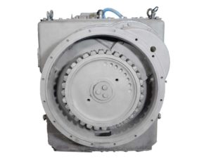
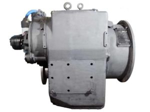
Proper inspection and replacement of bearings and gears in the Twin Disc MG-540 marine gear is crucial for ensuring optimal performance and avoiding catastrophic failures. These components experience intense loading, high rotational speeds, and harsh marine conditions. This comprehensive guide walks through the steps for identifying noise and wear, using specialized techniques to remove and install parts, inspecting gears under real load, and resetting gear lash correctly to factory specifications.
Identifying Bearing Noise or Gear Wear For Twin Disc MG-540 Marine Gear
Common Symptoms of Bearing Failure
- High-pitched whining at idle or load
- Clunking or rhythmic knocking under load
- Vibration that intensifies with RPM
- Excessive heat around bearing housings
Technicians should use a mechanic’s stethoscope or an ultrasonic listening device to locate the origin of noise while the gear is running at idle. Confirm with oil analysis for metal particles.
Physical Inspection Criteria:
- Rough Rotation: Spin the bearing in hand; any grating or vibration indicates replacement is necessary.
- Surface Damage: Check for pitting, spalling, and scoring on the raceway.
- Burn Marks: Blueing or discoloration indicates overheating or lubrication loss.
- Cage Deformation: Inspect ball/roller cages for warping or fractures.
Recognizing Gear Wear Patterns
The MG-540 uses hardened, carburized, and precision-ground helical gears that are in constant mesh. Look for:
- Pitting or microcracking on the tooth surface.
- Hook wear, where the gear tooth is worn into a hook shape.
- Tooth profile deformation that no longer matches the ideal involute shape.
- Edge loading or contact pattern misalignment, often caused by improper shaft spacing.
Use gear marking compound to evaluate contact patch under no load. If tooth contact occurs only at tips or edges, investigate misalignment or bearing wear.
Pulling and Pressing Techniques for Bearing Replacement
Replacing bearings on the MG-540 requires specialized tools and thermal control. Bearings include tapered roller and cylindrical types and are mounted with tight tolerances.
Required Tools
| Tool | Function |
| T-16240-1 | Output gear and bearing race remover |
| T-16240-2 | Input gear bearing end play gauge |
| T-15311 | Output bearing inner race installer |
| Bearing Heater or Induction Heater | Expands inner races safely |
| Press with Dial Gauge | Ensures square seating during installation |
Important: Never reuse removed bearings, even if they appear undamaged.
Bearing Removal
- Use bearing pullers or pushers designed for the bearing type.
- Support shafts or housings evenly to avoid cracking casting.
- For stuck races, apply heat (up to 250°F / 120°C) to expand the race.
- If removal requires more than 25 tons of force, inspect for shaft damage before proceeding.
Bearing Installation
- Clean and lightly oil the mating surfaces.
- Heat bearing cones in an oven to 250°F, or use an induction heater.
- Align and press using tools like T-15311 or T-21552-188/191 (seal and race installers).
- Ensure full seating by rotating the component during pressing.
Do not use hammers or metal punches—they damage precision surfaces.
Gear Inspection Under Load and at Idle
Gears should be evaluated both statically and during engine operation.
Static Inspection
- Remove top cover and inspect for:
- Metal dust
- Gear tooth scoring
- Deformed gear mesh
- Rotate output shaft by hand and check for smooth rotation without binding.
Load Testing Procedure
- Run the engine at idle (≤1800 RPM).
- Shift through forward, neutral, and reverse with load applied (dockline or thrust).
- Use a stethoscope to listen to:
- Gear-tooth chatter (indicative of misalignment or lash issues)
- Whining at consistent RPM (potential bearing preload issue)
- Check oil pressure for stability during shifts.
Key pressure specs during gear engagement:
- Primary and Secondary Clutch: 226–265 psi
- Lube Pressure: 27–78 psi depending on speed and gear ratio
Monitor temperature: Gear oil should not exceed 200°F during prolonged load testing.
Proper Installation Sequence to Maintain Gear Lash
Correct gear lash prevents excessive noise, heat generation, and tooth wear. The MG-540 uses shims at several bearing locations to establish spacing between gear pairs.
Lash Control Zones
| Component | Lash Control Method |
| Input Pinion/Gear | Shims between retainer and housing |
| Clutch Pinions | Shims behind output pinion bearing cups |
| Output Gear | Preload shims at seal carrier flange |
Step-by-Step Procedure
- Install Test Shims:
- Use a known thickness to allow slight lash.
- Use a known thickness to allow slight lash.
- Mount Gears:
- Use heated method or press-fit with alignment tools.
- Use heated method or press-fit with alignment tools.
- Check Gear Lash with Dial Indicator:
- Ideal lash range: 0.003″ to 0.008″
- Rotate shaft 360° and measure backlash at three positions.
- Adjust Shims as Needed:
- Increase shim stack to increase lash.
- Reduce shim thickness to tighten lash (within limits).
Gear contact pattern should show even contact across center third of each tooth face. Use bluing compound to confirm tooth contact under light pressure rotation.
Tolerance and Preload Specifications
Refer to the following factory-specified tolerances when assembling or validating gear and bearing setups:
Bearing End Play
| Component | Min (in) | Max (in) |
| Input Pinion | 0.0005 | 0.003 |
| Input Gear | 0.0005 | 0.003 |
| Primary Shaft | 0.0005 | 0.003 |
| Secondary Shaft | 0.0005 | 0.003 |
| Output Shaft | 0.003 | 0.006 |
Preload Torque (Pinions)
- Primary and Secondary: 25 lb-in (2.82 Nm) measured with torque wrench adapter (Tool T-17473)
Final Verification Before Reassembly
Use the following checklist:
Task |
Confirmed |
| All bearings spin freely and silently | ✅ |
| Gear lash within 0.003–0.008 inches | ✅ |
| Preload torque verified on pinions | ✅ |
| Gears seated on taper with no axial movement | ✅ |
| Contact pattern confirms central meshing | ✅ |
| Shims installed per specification | ✅ |
| Fasteners torqued and thread-locked | ✅ |
Summary
Inspecting and replacing bearings and gears in the Twin Disc MG-540 marine transmission is a precise mechanical procedure that demands strict adherence to measurement, alignment, and assembly protocols. By identifying early signs of wear, following correct pulling/pressing techniques, and maintaining gear lash and preload per OEM spec, technicians ensure optimal performance and a long service life.
Videos About Twin Disc Transmissions
6 Reasons Your Twin Disc Transmission Has Low Oil Pressure
7 Reasons Your Twin Disc Transmission Is Overheating
3 Reasons Your Clutch Plates in Your Twin Disc Transmission Are Making Excessive Noise
Bull Gear On A Twin Disc Transmission
Rebuilt Twin Disc Transmissions