

 Free US Calls: 1-888-433-4735
 International: 305-545-5588

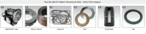
Parts Catalog for Twin Disc MG521 Marine Transmissions
Rebuilt Twin Disc MG521 Marine Transmissions
Plate Kit For Twin Disc MG521 Marine Transmission
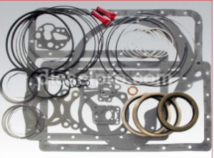
Gasket Kits For Twin Disc MG521 Marine Transmission
Recognizing Signs of Wear or Damage in the MG521
Effective maintenance begins with early detection. Understanding the signs of bearing or gear wear allows operators and technicians to schedule repairs before a minor issue becomes a catastrophic failure. Here are the most common warning signs that indicate it’s time to inspect the internal components of your Twin Disc MG521 marine transmission.
1. Abnormal Noise
- Whining or humming: Typically indicates worn bearings or misalignment between gears.
- Grinding: Suggests broken gear teeth, metal-to-metal contact, or a loss of lubrication.
- Clicking or rattling: Often due to loose gear lash, cracked bearing races, or worn couplings.
These noises tend to intensify under load or at specific RPMs.
2. Excessive Heat
- Surface temperatures over 200°F at the gear housing signal excessive friction.
- Heat can damage clutch plates, warp gear teeth, and degrade seals.
- Consistent overheating may stem from a failing bearing or insufficient oil circulation.
3. Metal Shavings or Debris in Oil
- Metallic particles on the magnetic drain plug or inside the oil filter are red flags.
- Bronze or copper flecks may indicate thrust washer or bushing wear.
- Grey, paste-like sludge suggests aluminum or soft-metal galling from bearings.
Any time foreign material is found in the oil, a teardown should be scheduled immediately.
Disassembly Procedure for the MG521
Before beginning disassembly, ensure the vessel is out of operation, the transmission is isolated from the engine, and all fluids are drained. This is a multi-step process that requires both mechanical knowledge and the right tools.
1. Tools and Equipment Required
- Socket and wrench sets (SAE and metric)
- Gear pullers and bearing separators
- Snap ring pliers
- Torque wrench
- Shop press (for bearing removal/installation)
- Soft-faced hammer
- Dial indicator and magnetic base
- Oil catch pans, rags, and PPE
2. Safety Preparation

- Disconnect all hydraulic and control lines.
- Label or photograph wiring connections before removal.
- Drain all oil into appropriate waste containers.
- Wear eye protection and gloves.
- Use lifting equipment rated for the gear’s weight (400–550 lbs).
3. Disassembly Steps
- Remove Output Flange: Use a flange puller or press as needed.
- Detach Oil Cooler Lines and Filter Housing: Drain any residual oil from these areas.
- Remove Bell Housing Bolts: Separate from engine if still mounted.
- Open Inspection Covers: Begin with the top to inspect for gear wear.
- Remove Input Shaft Assembly: Carefully extract using slide hammer or press.
- Extract Clutch Assemblies and Intermediate Shafts: Label each component.
- Disassemble Gear Sets: Carefully remove bearings and thrust washers with a press or gear puller.
- Inspect each part as removed: Do not wait until all components are out before inspection.
Keep all shims and spacers organized—they are critical for reassembly and gear backlash tolerances.
Gear Tooth Inspection – Pitting, Wear, Scoring
Gear health is determined by visual and dimensional inspection. Damage to the gear teeth can compromise the transmission’s ability to carry load and maintain synchronization.
1. Visual Inspection Checklist
- Pitting: Small craters or divots in the tooth surface caused by surface fatigue.
- Scoring: Long scratches or gouges, often caused by debris or low lubrication.
- Tooth Wear: Rounded edges, wear at the pitch line, or thinning—reduces load capacity.
- Chipping or Cracking: Usually due to shock loading or metal fatigue.
- Misalignment Wear: Uneven tooth wear across gear face width.
2. Acceptable Wear Limits
If gear tooth pitting is shallow and doesn’t exceed 20% of the surface, continued operation may be acceptable with monitoring. Any of the following require replacement:
- Crack lines visible with dye penetrant testing
- Broken or missing gear teeth
- Deep pitting or scoring across multiple teeth
- Excessive backlash (>0.015” in most models)
Use gear marking compound or bluing to observe load pattern across teeth during contact testing.
Measuring Bearing Play and End Float
Bearings in the MG521 support the rotating shafts under extreme pressure. Over time, they can develop internal looseness, resulting in vibration, shaft misalignment, and gear miscontact.
1. Radial Play Check
- Use a dial indicator set perpendicular to the shaft.
- Gently rock the shaft and record deflection.
- Acceptable radial play for tapered roller bearings is typically <0.002”.
2. End Float (Axial Play)
- Mount dial indicator parallel to shaft.
- Push and pull shaft in axial direction.
- Measure total movement.
End float limits vary, but excessive play (>0.005”–0.008”) indicates worn bearing cups or excessive thrust washer wear.
3. Bearing Surface Inspection
- Check for scoring, discoloration, or flaking on rollers and races.
- Blue heat spots suggest overheating.
- Rust-colored patches can indicate water intrusion or oil contamination.
Bearings should always rotate smoothly by hand with no grit or catch. If in doubt—replace.
Cleaning Procedures for Removed Components
Before reassembling or reusing any gear or bearing, all parts must be thoroughly cleaned and inspected. Even microscopic grit can cause long-term damage in a high-load gearbox like the MG521.
1. Cleaning Process
- Soak components in solvent or degreaser (kerosene or brake cleaner).
- Scrub using brass or nylon brushes to avoid damaging machined surfaces.
- Use compressed air to dry completely.
- Avoid spinning bearings with compressed air—it can over-speed and damage them.
2. Special Considerations
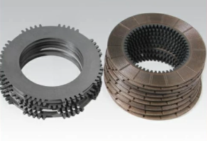
- Avoid soaking friction plates or clutch discs.
- Use ultrasonic cleaning only for steel components without bonded surfaces.
- Gears should be coated in rust-preventive oil after cleaning if not reinstalled immediately.
Inspect all cleaned parts again under bright lighting before reuse.
Installing New Gears and Bearings in the MG521
Once all damaged or worn components have been removed, and replacements sourced (preferably from Diesel Pro Power’s premium aftermarket line), installation must be carried out with attention to factory clearances and alignment.
1. Bearing Installation
- Use a shop press or bearing heater (not hammering).
- Freeze shaft or heat bearing slightly to aid press-fit.
- Ensure proper seating against shoulders.
- Lubricate with light assembly oil before installation.
2. Gear Installation
- Align keyways or splines carefully.
- Tap into place using a soft mallet and wood block.
- Ensure gears sit flush against shoulders or spacers.
- Replace all thrust washers and check alignment.
Use shims where required to maintain correct axial play and tooth engagement patterns.
3. Lubrication Before Startup
- Coat bearings and gears with transmission assembly lube or oil.
- Ensure no dry metal-to-metal surfaces remain inside the case.
Rechecking Gear Backlash and Alignment
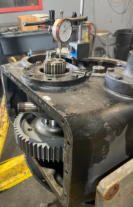
Technician uses a starrett dial indicator to measure the backlash between the gears on a Detroit Diesel engine.
Proper backlash between mating gears ensures smooth engagement and wear distribution. Too little backlash can cause overheating and seizure. Too much causes clunking and gear lash noise.
1. Measuring Backlash
- Mount dial indicator on stationary gear face.
- Rock the mating gear back and forth.
- Read total indicator movement (should be within 0.004”–0.012” depending on gear size).
2. Adjusting Backlash
- Add or subtract shims behind bearing cups to move gears closer or farther apart.
- Recheck after each adjustment—trial fit and measure again.
3. Gear Tooth Contact Pattern
- Apply gear marking compound (Prussian blue).
- Rotate gears slowly under light load.
- Observe contact area and adjust shim stack if necessary.
Ideal contact pattern should be centered and full across the tooth face.
Reassembly and Torque Specs for the MG521
Once all components have been inspected, replaced, and aligned, reassembly must be methodical. Use new gaskets, seals, and threadlockers where required.
1. Gasket and Seal Replacement
- Always install new shaft seals and gaskets (included in Diesel Pro rebuild kits).
- Use sealant sparingly—overuse can block oil galleries.
- Pre-lube seals and rotate shafts during installation to seat properly.
2. Fastener Torque Table
Component |
Torque (lb-ft) |
| Bell Housing Bolts | 75–85 |
| Shaft Retaining Nuts | 150–180 |
| Flange Bolts | 80–100 |
| Bearing Cap Bolts | 35–50 |
| Cover Bolts (Oil Tight) | 25–35 |
Use a calibrated torque wrench and always torque in a cross pattern.
3. Final Reassembly Steps
- Replace oil filter and install filter housing.
- Attach oil cooler lines and control hoses.
- Fill transmission with oil and allow 10–15 minutes for settling.
- Rotate input shaft by hand to pre-lube components.
- Reinstall inspection covers and test for smooth rotation before engine start.
Post-Repair Testing and Diagnostics
After the MG521 is reassembled, the unit must be tested under controlled conditions before returning to service. This testing phase is critical for confirming successful repairs and identifying any missed issues.
1. Dry Run and Leak Check
- Start engine with gear in NEUTRAL.
- Monitor oil pressure within first 5–10 seconds.
- Allow to idle for 10–15 minutes.
- Inspect for leaks at:
- Shaft seals
- Filter housing
- Cover gaskets
- Control fittings
Shut down if pressure is low or oil leaks are visible.
2. Engagement Testing
- Shift into FORWARD, hold for 10 seconds, return to NEUTRAL.
- Repeat with REVERSE.
- Confirm smooth engagement with no delay or clunking.
- Note any lag or hesitation—these could indicate clutch wear or oil pressure problems.
3. Vibration and Noise Monitoring
- Use an IR thermometer to track heat build-up at bearings.
- Listen for any high-pitched whines, gear clash, or irregular humming.
- Compare oil pressure and temperature to pre-repair readings.
4. Sea Trial (Optional)
If practical, conduct a brief under-load test at the dock or during sea trial:
- Observe shift engagement under load.
- Monitor oil temperature, pressure, and system response.
- Check for vibration at various RPMs.
- Record all findings and log in the maintenance book.
Conclusion: Long-Term Reliability Through Precision Repair
The MG521 is a battle-tested marine transmission capable of thousands of hours of operation—but only when maintained and repaired with precision. Gears and bearings are the heart of the transmission, and their health determines the reliability of the entire vessel.
By carefully inspecting, measuring, replacing, and reassembling these components, you protect your investment and ensure uninterrupted operation on the water.
Diesel Pro Power offers complete rebuild kits for the MG521 that include:
- Bearings, seals, gaskets, shims, and filters
- Detailed product support
- OEM-equivalent or better quality
- Fast shipping and expert guidance
Rebuilt Twin Disc MG521 Marine Transmissions
Plate Kit For Twin Disc MG521 Marine Transmission
Gasket Kits For Twin Disc MG521 Marine Transmission
Videos About Twin Disc Transmissions
6 Reasons Your Twin Disc Transmission Has Low Oil Pressure
7 Reasons Your Twin Disc Transmission Is Overheating
3 Reasons Your Clutch Plates in Your Twin Disc Transmission Are Making Excessive Noise
Bull Gear On A Twin Disc Transmission
Rebuilt Twin Disc Transmissions