For marine professionals and vessel owners relying on the Twin Disc MG5114A, understanding what happens inside the gearcase is critical for ensuring long-term transmission health. Internal inspections are necessary during:
- Scheduled overhauls (typically every 5,000–10,000 hours)
- Symptom-based diagnostics (slipping, noise, or oil contamination)
- Used gear purchases or rebuilt transmission quality checks
This section outlines best practices for inspecting clutch packs, gear teeth, bearings, output shafts, and oil seals inside the MG5114A transmission. It assumes the transmission is out of the vessel, drained of oil, and safely disassembled on a workbench or transmission stand.

Parts Catalog for Twin Disc MG5114A Marine Transmissions
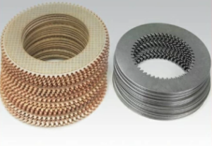
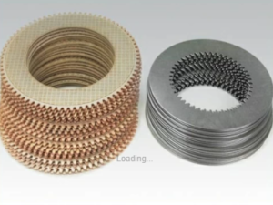
Plate Kit For Twin Disc MG5114A Marine Transmission
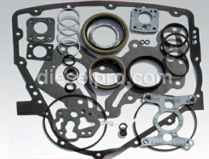
Gasket Kits For Twin Disc MG5114A Marine Transmission
Clutch Pack Inspection

Understanding the Clutch Packs
The MG5114A contains two clutch packs—one for forward and one for reverse. These hydraulic multi-disc assemblies allow smooth engagement of each gear via pressure from the internal oil pump.
Each pack consists of:
- Friction discs (clutch plates) – Typically lined with high-friction material
- Steel separator plates – Provide structural support and contact surfaces
- Apply pistons – Push plates together when hydraulic pressure is applied
- Snap rings or retainers – Maintain stack alignment
Signs of Wear or Heat Damage
Even with perfect oil and pressure, clutch packs wear over time due to:
- Constant gear changes
- Improper fluid selection
- Overheating
- Hydraulic pressure fluctuation
During inspection:
- Remove clutch packs carefully, noting order and orientation.
- Inspect friction discs for:
- Burnt surfaces
- Glazing or dark blue patches (signs of overheating)
- Uneven wear patterns
- Worn friction material exposing the base plate
- Inspect separator plates for:
- Warping (check on glass or flat surface)
- Heat bluing or scoring
- Cracks or brittle spots
- Measure clutch disc thickness with a micrometer and compare to OEM minimum specs.
- Smell for signs of burnt friction—indicates slippage under load.
Field tip: Even if the discs look “okay,” excessive hours or minor slipping can affect performance. Don’t reuse marginal parts.
Replacement Guidelines
- Always replace clutch packs as a matched set—never mix new and old friction plates.
- Replace steel separator plates if scored, blued, or warped.
- If piston seals are removed or worn, replace all O-rings and gaskets as a kit.
- Use assembly lube or clean transmission oil during reassembly.
- Confirm plate order matches service documentation.
- Verify free movement in the drum before final installation.
Gear Teeth and Bearing Condition
Inspecting the Gear Train
The MG5114A uses a helical gear arrangement designed for smooth torque transfer and quiet operation. These gears rotate at high speeds and must maintain exact tolerances to prevent vibration, noise, and tooth failure.
Gears to inspect include:
- Input gear – Attached to the input shaft
- Intermediate and reduction gears – Transfer torque
- Output gear – Connects to the output shaft and propeller system
Pitting, Scoring, or Spalling
During inspection, clean gears with degreaser or parts washer, then:
- Use a bright LED flashlight and magnifier for surface defects
- Rotate gears slowly and inspect each tooth profile
- Look for:
- Pitting – Small surface craters or corrosion (usually due to contaminated oil)
- Scoring – Deep scratches or gouges from debris or poor lubrication
- Spalling – Flaking of the gear material, often from subsurface fatigue
- Tooth deformation – Bending, rounding, or shearing of gear teeth
Critical: Even one cracked or missing tooth means the gear must be replaced. No exceptions.
Proper Visual Inspection Techniques
- Clean gear teeth with lint-free rags to avoid embedding fibers
- Rotate shafts slowly by hand to inspect entire circumference
- Use bluing dye or gear marking compound to assess contact patterns
- Check for lash and alignment against a test dial indicator or feeler gauge
A loud whining or grinding in operation is often traced back to gear tooth alignment or wear.
Bearing Inspection
Bearings support all rotating shafts in the gear. Inspect:
- Input bearing
- Intermediate support bearings
- Output shaft bearing
Look for:
- Scoring or pitting on raceways
- Noise or roughness when rotated by hand
- Loose fit in the bore
- Brinelling marks – Small indentations from impact or vibration
- Discoloration or overheating
Spin the bearings slowly in hand:
- They should be smooth and silent.
- Any “gritty” or metallic feel requires replacement.
Always replace bearings with correct-load, marine-grade equivalents (consult OEM bearing numbers).
Output Shaft and Oil Seals
Output Shaft Wear and Inspection
The output shaft transfers torque from the gear to the propeller shaft. Because it’s exposed to torque, misalignment, and seawater exposure, this component must be flawless.
Steps:
- Clean the shaft completely
- Inspect:
- Shaft splines – Look for wear, fretting, or distortion
- Keyways – Check for elongation, cracks, or burrs
- Sealing surfaces – Must be free of grooves, pitting, or rust
- Runout check:
- Use a dial indicator mounted to a bench
- Rotate the shaft and measure total indicated runout
- Acceptable runout is typically under 0.002–0.003 inches
If seal surfaces are grooved, use a speedi-sleeve to restore smooth sealing.
Endplay Checks
Excessive shaft endplay can:
- Destroy seals
- Affect gear mesh
- Create vibration or backlash
How to check endplay:
- Set a dial indicator against the output shaft end
- Push and pull the shaft axially
- Measure total travel
- Compare against OEM spec (commonly under 0.010 inches)
If endplay exceeds limits:
- Inspect thrust washers or spacers
- Replace or shim bearings to restore proper tolerance
Oil Seals: Wear and Replacement Advice

Input and Output Shaft Seals
Oil seals prevent hydraulic fluid from escaping the gear housing. On the MG5114A, key seal points include:
- Input shaft seal – Located at the front, where the transmission mates with the engine
- Output shaft seal – Seals the shaft coupling at the rear
- Selector shaft or valve seals – In some variants with mechanical control
Signs of Seal Wear
- Oil leaks around shaft openings
- Oil trails along housing edges
- Evidence of weeping around the dipstick or vent
- Visible cracks, hardening, or pitting on the seal lip
- Emulsified oil in the bilge
Replacement Process
- Carefully remove the seal with a puller tool
- Inspect the shaft surface—repair or replace if grooved
- Clean the seal bore
- Apply oil or sealant to new seal outer edge
- Install using a seal driver or evenly seated press
- Lubricate the inner lip with clean oil before startup
Never hammer a seal in with a punch—it causes micro-cracks and uneven sealing pressure.
Best Practices:
- Replace seals any time the shaft is removed or the gear is rebuilt
- Use OEM or high-quality aftermarket seals made for marine temperature and pressure ranges
- Always inspect mating surfaces—a perfect seal depends on perfect metal
- Consider using double-lip seals for vessels in high-salt environments
Common Internal Inspection Mistakes to Avoid
| Mistake | Consequence | Proper Approach |
| Reusing old clutch discs | Slippage, overheating | Replace as a set with new separator plates |
| Skipping gear lash check | Noise, gear wear | Use feeler gauge or dial test indicator |
| Not inspecting bearings | Catastrophic failure | Rotate by hand and check for noise/roughness |
| Reinstalling grooved shafts without repair | Seal leaks | Install a speed sleeve or replace the shaft |
| Improper seal installation | Premature leaks | Use seal driver and light oil on install |
Final Notes: When to Rebuild vs Replace
Inspecting internal components helps determine whether your MG5114A:
- Needs a full rebuild (all clutches, bearings, seals, and gaskets)
- Can be restored with minor component replacement
- Should be swapped for a remanufactured unit
Rebuild If:
- Clutch pack shows wear but gears and shafts are intact
- Bearings are noisy but not seized
- Seals have hardened or started leaking
- Housing and gearset pass visual inspection
Replace If:
- Gear teeth are chipped, pitted, or cracked
- Shaft runout is excessive
- Housing is cracked or warped
- Transmission has exceeded 15,000 hours with multiple prior failures
Diesel Pro Power offers remanufactured Twin Disc MG5114A units and premium aftermarket clutch kits, bearings, and seal kits to match OEM performance.

Plate Kit For Twin Disc MG5114A Marine Transmission
Gasket Kits For Twin Disc MG5114A Marine Transmission
Videos About Twin Disc Transmissions
6 Reasons Your Twin Disc Transmission Has Low Oil Pressure
7 Reasons Your Twin Disc Transmission Is Overheating
3 Reasons Your Clutch Plates in Your Twin Disc Transmission Are Making Excessive Noise
Bull Gear On A Twin Disc Transmission
Rebuilt Twin Disc Transmissions


 Free US Calls: 1-888-433-4735
 International: 305-545-5588