

 Free US Calls: 1-888-433-4735
 International: 305-545-5588
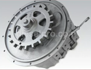
The Twin Disc MG506 Marine Gear is designed for reliable, long-lasting performance in marine environments. However, its performance and longevity depend heavily on proper installation. Even minor errors during installation can lead to misalignment, vibration, excessive wear, or early failure. This guide provides a comprehensive step-by-step approach to installing the MG506 transmission, ensuring optimal performance and safety.
Pre-Installation Checklist
Before beginning the installation of the Twin Disc MG506 Marine Gear, it’s essential to prepare thoroughly. The following checklist ensures that you have the right conditions, tools, and information for a successful installation.
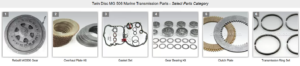
Parts Catalog for Twin Disc MG506 Marine Transmissions
Rebuilt Twin Disc MG506 Marine Transmissions
Bearings For Twin Disc MG506 Marine Transmissions
Plate Kit For Twin Disc MG506 Marine Transmission
Gasket Kits For Twin Disc MG506 Marine Transmission
1. Review Installation Manual
- Carefully read through the official service and installation manual provided by Twin Disc. Although this guide covers critical points, always cross-reference with the manufacturer’s instructions.
- Identify any specific recommendations or requirements for the vessel’s engine setup and space constraints.
2. Inspect Components
- Check the MG506 Transmission: Ensure it is free from damage, corrosion, or manufacturing defects. Inspect seals, shafts, and mounting surfaces.
- Inspect Engine Coupling Components: Verify that couplings, bolts, and hardware match the specifications for the MG506.
- Review Vessel’s Engine Compartment: Ensure there’s enough clearance for mounting, maintenance access, and fluid connections.
3. Verify Alignment Compatibility
- Ensure the engine and propeller shaft align correctly with the transmission to avoid stress or misalignment during operation.
- Use precision alignment tools to measure any deviations before starting the installation.
4. Check Mounting Structure
- Inspect engine beds or mounting frames to ensure they are structurally sound, level, and clean.
- Verify the surface is free from corrosion, oil, or debris that could compromise mounting stability.
5. Gather Required Materials
- Ensure that all necessary materials—like mounting hardware, lubricants, and gaskets—are available.
- Confirm that the correct fluid type and quantity for the MG506 transmission are ready for use.
Tools and Equipment Required

Having the right tools and equipment on hand is essential for an efficient and error-free installation. Using improper or makeshift tools can lead to incorrect installation and future issues.
Standard Tools
- Torque wrench (calibrated for accurate torque application)
- Socket set with deep sockets (metric and standard sizes)
- Open-ended wrenches
- Screwdrivers (flathead and Phillips)
- Allen wrenches or hex keys
- Thread-locking compound (if specified)
Specialized Tools
- Alignment Tool: Essential for aligning the engine and propeller shaft correctly.
- Dial Indicator: For precision alignment and detecting shaft deviations.
- Feeler Gauges: To check clearance tolerances between components.
- Hydraulic Lift or Engine Hoist: To safely lift and position the transmission.
- Coupling Puller: If replacing an existing transmission.
Safety Equipment

- Safety gloves
- Protective eyewear
- Steel-toed boots
- Hearing protection (if working in noisy environments)
Consumable Supplies
- Marine-grade lubricants and sealants
- Replacement gaskets or seals
- Cleaning solvents for mounting surfaces
- Rags or wipes for cleaning
- Anti-corrosion spray for metal parts
Mounting Procedures
Proper mounting ensures that the transmission operates smoothly, with minimal vibration and reduced wear. Here’s a detailed guide for securely mounting the Twin Disc MG506.
1. Prepare the Mounting Surface
- Clean the mounting surface thoroughly to remove oil, dirt, and debris.
- Inspect for any surface irregularities. Grind or smooth out imperfections to avoid alignment issues.
- Apply an anti-corrosion spray if the installation environment is prone to rust.
2. Position the Transmission
- Using a hydraulic lift or hoist, carefully position the MG506 onto the engine bed.
- Align the transmission input shaft with the engine’s output shaft. Ensure that the shafts are level and not at an angle.
- Take care to avoid any damage to the shaft splines or mounting faces during this process.
3. Secure Mounting Bolts
- Apply thread-locking compound to the mounting bolts to prevent loosening due to vibrations.
- Install and hand-tighten the mounting bolts to hold the transmission in place.
- Using the torque wrench, tighten bolts in a crisscross pattern to the manufacturer’s specified torque rating. This ensures even distribution of pressure.
Tip: Over-tightening can cause thread stripping or casing damage, while under-tightening can lead to loosening during operation. Use a calibrated torque wrench for precision.
4. Check for Vibration Isolation
- Install vibration dampening mounts if specified. These mounts reduce mechanical stress and extend the lifespan of both the engine and transmission.
- Ensure that the mounts are level and seated correctly.
Alignment Guidelines
Proper alignment between the engine, transmission, and propeller shaft is crucial. Misalignment can result in excessive vibration, noise, and even premature failure of transmission components.
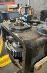
1. Check Initial Alignment
- Before securing the transmission fully, check the initial alignment using a dial indicator.
- Measure the runout (deviation) of the engine and transmission shafts to ensure they are concentric and parallel.
2. Conduct Parallel Alignment
- Place the dial indicator on the propeller shaft flange and rotate the assembly.
- Adjust the position of the transmission until the shaft alignment is within acceptable tolerances, usually less than 0.003 inches (0.076 mm) for optimal performance.
3. Conduct Angular Alignment
- Measure the angle between the transmission flange and the engine flange using feeler gauges.
- Adjust the position of the engine or transmission slightly to reduce the angle gap. Consistent readings at all positions indicate correct alignment.
4. Final Torque of Mounting Bolts
- Once alignment is confirmed, tighten all mounting bolts to the final torque specification.
- Recheck alignment after final torqueing to ensure no shifts occurred during the tightening process.
Fluid Connection Procedures
Proper fluid connections are critical for the lubrication and cooling systems of the MG506. Here’s how to ensure correct fluid connection and filling.
1. Install Oil Cooler (If Applicable)
- Mount the oil cooler in a location with sufficient airflow.
- Ensure that the cooler’s inlet and outlet ports align correctly with the transmission lines.
2. Connect Fluid Lines
- Attach the hydraulic fluid lines using marine-grade hoses resistant to high temperatures and pressure.
- Secure hose connections using high-pressure clamps or threaded fittings, ensuring a tight, leak-free fit.
- Avoid sharp bends in hoses to ensure optimal fluid flow.
3. Fill Transmission with Lubricant
- Add the specified transmission fluid through the fill port.
- Monitor the fluid level using the transmission’s dipstick or level indicator.
- Ensure fluid reaches the manufacturer’s recommended level without overfilling.
4. Bleed the System
- Run the engine briefly to allow fluid to circulate through the transmission and cooler.
- Check fluid levels again and top off as necessary.
- Inspect all fluid connections for leaks and tighten any loose fittings.
Final Inspection Before Initial Operation
A final inspection ensures that the MG506 is ready for safe and efficient operation. Skipping this step could result in damage or performance issues.
1. Verify Mounting Security
- Recheck that all mounting bolts are torqued to specification.
- Ensure vibration dampening mounts are secure and correctly positioned.
2. Confirm Alignment
- Perform a final alignment check, ensuring that both angular and parallel alignments are within tolerance.
- Confirm that no shifts occurred during the final torqueing process.
3. Inspect Fluid Levels
- Verify that the transmission fluid is at the correct level after system bleeding.
- Check for signs of leaks around all hose connections and seals.
4. Test Electrical Connections
- If the transmission has integrated electronic controls, test the connections and ensure proper function.
- Confirm that sensors, alarms, or control units are operational.
5. Check Safety Mechanisms
- Ensure that safety interlocks are functioning correctly to prevent accidental engagement.
- Test emergency shutdown systems if applicable.
6. Perform Initial Startup
- Start the engine and observe the transmission for any abnormal vibrations or noises.
- Allow the system to reach operating temperature and check fluid pressures and temperatures.
- Shift the transmission through all gears to ensure smooth engagement.
Conclusion
By following this detailed installation guide, you can ensure that the Twin Disc MG506 Marine Gear is installed correctly and operates at peak efficiency. Taking the time to adhere to proper mounting, alignment, and fluid procedures reduces the risk of operational failures, extends the lifespan of the transmission, and ensures safety during marine operations.
Regular maintenance and periodic inspections are essential to keep the MG506 running smoothly for years to come.
Rebuilt Twin Disc MG506 Marine Transmissions
Bearings For Twin Disc MG506 Marine Transmissions
Plate Kit For Twin Disc MG506 Marine Transmission
Gasket Kits For Twin Disc MG506 Marine Transmission
Videos About Twin Disc Transmissions
6 Reasons Your Twin Disc Transmission Has Low Oil Pressure
7 Reasons Your Twin Disc Transmission Is Overheating
3 Reasons Your Clutch Plates in Your Twin Disc Transmission Are Making Excessive Noise
Bull Gear On A Twin Disc Transmission
Rebuilt Twin Disc Transmissions