

 Free US Calls: 1-888-433-4735
 International: 305-545-5588

Key Points in This Article
- Installation Guide for Twin Disc MG514C Marine Gear
- Pre-Installation Checklist
- Tools and Equipment Required
- Mounting Procedures
- Alignment Procedures
- Initial Lubrication
- Final Inspection and Testing
- Conclusion
Proper installation of the Twin Disc MG514C Marine Gear is crucial for ensuring reliable performance and long service life. Incorrect installation can lead to operational failures, excessive wear, and costly repairs. This comprehensive guide provides step-by-step instructions, from pre-installation preparation to final inspection and testing. By adhering to these guidelines, technicians and marine engineers can ensure optimal installation and alignment, promoting efficiency and durability.
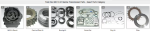
Parts Catalog for Twin Disc MG514C Marine Transmissions
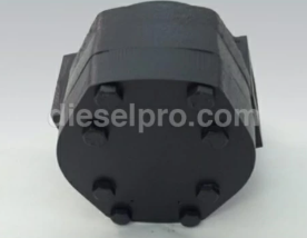
Rebuilt Twin Disc MG514C Marine Transmissions
Bearings For Twin Disc MG514C Marine Transmissions
Plate Kit For Twin Disc MG514C Marine Transmission
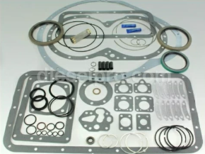
Gasket Kits For Twin Disc MG514C Marine Transmission
Pre-Installation Checklist
Before beginning the installation of the Twin Disc MG514C, it is critical to prepare adequately. Ensuring that the installation environment, equipment, and components are ready will streamline the process and reduce the risk of errors.
1. Review Documentation
- Read the Service Manual: Thoroughly read the Twin Disc MG514C service manual to understand specifications, torque settings, and safety recommendations.
- Installation Drawings: Review detailed installation diagrams to ensure correct positioning and alignment.
- Manufacturer Recommendations: Check for any manufacturer-specific notes or recent service bulletins that may affect the installation.
2. Verify Component Integrity
- Inspect the Transmission: Examine the Twin Disc MG514C for any signs of damage during shipping. Look for dents, cracks, or loose components.
- Check Part Numbers: Verify that the transmission model and serial number match the intended engine and vessel specifications.
- Review Mounting Components: Inspect the condition of mounting bolts, alignment tools, and gaskets.
3. Prepare Installation Site
- Clean and Dry Area: Ensure the installation area is clean, dry, and free of debris.
- Organize Tools: Place tools and components within easy reach to avoid delays during the installation process.
- Safety Protocols: Establish safety measures, including the use of personal protective equipment (PPE) and marking off hazardous zones.
4. Confirm Engine Compatibility
- Inspect Engine Output Shaft: Verify that the engine output shaft matches the transmission input coupling in size and alignment specifications.
- Confirm Torque Specifications: Check that the engine’s torque output does not exceed the Twin Disc MG514C’s rated capacity.
5. Assess Lifting and Support Equipment
- Lifting Devices: Ensure hoists, cranes, or forklifts are rated for the transmission’s weight and are in good working condition.
- Stabilization Tools: Prepare stands, blocks, or supports to stabilize the transmission during installation.
Tools and Equipment Required
Proper tools and equipment are essential for a successful installation. Using incorrect or substandard tools can lead to errors, equipment damage, or safety hazards.
1. Essential Tools

- Torque Wrench: For tightening bolts to the manufacturer’s recommended specifications.
- Standard Wrenches and Sockets: For general assembly tasks.
- Hydraulic Jack: To assist with positioning and securing the transmission.
- Alignment Tool: To ensure precise alignment between the engine and transmission.
- Dial Indicator: For measuring alignment tolerances.
- Feeler Gauges: To verify correct clearances between mating components.
- Hoist or Crane: For lifting and positioning the transmission.
2. Measuring Instruments
- Vernier Caliper: To measure shaft diameters and alignment tolerances.
- Spirit Level: For ensuring level positioning of the transmission.
- Plumb Bob: For vertical alignment checks.
3. Safety Equipment

- Personal Protective Equipment (PPE): Safety glasses, gloves, and steel-toe boots.
- Straps and Slings: For securing the transmission during lifting.
- Fire Extinguisher: In case of accidental ignition from nearby equipment.
4. Consumables and Lubricants
- Lubricating Oil: As specified in the Twin Disc manual.
- Thread Sealant and Locking Compound: To secure bolts and prevent loosening during operation.
- Gaskets and Seals: Replacement parts if required during installation.
Mounting Procedures
Correct mounting is vital to ensuring the transmission’s secure placement and operational stability. The following steps outline how to safely mount the Twin Disc MG514C.
1. Positioning the Transmission
- Use Lifting Equipment: Carefully lift the Twin Disc MG514C using a crane or hoist. Attach lifting slings to the designated lifting eyes on the transmission.
- Center the Transmission: Align the transmission with the engine’s output shaft, ensuring it is centered for precise coupling.
- Lower Carefully: Gradually lower the transmission into position, taking care not to damage nearby components.
2. Securing the Mounts
- Align Bolt Holes: Ensure the bolt holes in the transmission align with those on the engine bell housing or mounting plate.
- Insert Mounting Bolts: Insert bolts by hand initially to avoid cross-threading.
- Tighten Securely: Use a torque wrench to tighten bolts to the specified torque values. Tighten in a cross-pattern to ensure even pressure distribution.
- Use Locking Compound: Apply thread-locking compound to prevent bolts from loosening during operation.
3. Verifying Stability
- Check for Movement: Attempt to rock the transmission gently. It should be secure and immobile.
- Inspect Mounting Surfaces: Ensure that there are no gaps or misalignments between the mounting surfaces.
- Re-torque if Necessary: After initial tightening, recheck torque values to ensure all bolts are secure.
Alignment Procedures
Proper alignment between the Twin Disc MG514C and the engine is critical for preventing vibration, component wear, and premature failure.
1. Initial Alignment Check
- Visual Inspection: Begin with a visual check to ensure the shafts appear aligned.
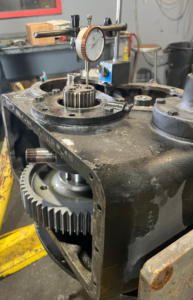
- Measure with Dial Indicator: Attach a dial indicator to the output flange and rotate the shaft to check for radial and axial runout.
- Use Feeler Gauges: Insert feeler gauges between the coupling faces to verify consistent spacing.
2. Aligning the Transmission
- Adjust Mounts: Loosen the mounting bolts slightly and adjust the transmission position as needed.
- Shim if Necessary: Use shims to achieve vertical alignment and eliminate angular misalignment.
- Check Horizontal Alignment: Measure the coupling face at multiple points around its circumference to ensure it is parallel to the engine face.
3. Final Alignment Verification
- Tighten and Recheck: Once aligned, tighten the mounting bolts and recheck measurements to ensure alignment has not shifted.
- Record Measurements: Document final alignment measurements for future reference.
Initial Lubrication
Lubrication is vital to reduce friction, prevent overheating, and ensure smooth operation. Follow these steps to lubricate the Twin Disc MG514C correctly.
1. Selecting the Correct Lubricant
- Consult Manufacturer Specifications: Use oil that meets or exceeds the manufacturer’s requirements, typically API GL-4 or GL-5.
- Check Oil Viscosity: Ensure the viscosity matches the expected operating temperatures.
2. Filling the Transmission
- Locate the Fill Port: Open the designated fill port on the transmission.
- Add Oil Gradually: Pour oil slowly to avoid overfilling. The Twin Disc MG514C generally requires 3 to 4 gallons of lubricating oil.
- Monitor Oil Levels: Use the dipstick to ensure the oil level reaches the recommended mark.
3. Check for Leaks
- Inspect Seals and Gaskets: Ensure there are no leaks around the fill port or seals.
- Run Preliminary Check: Rotate the input shaft manually to distribute oil and recheck for leaks.
Final Inspection and Testing
After installation, a thorough inspection and testing phase ensures the system is ready for operational use.
1. Visual Inspection
- Check All Bolts: Ensure all mounting and coupling bolts are tight and secure.
- Inspect Seals and Hoses: Look for any signs of leaks or misalignments.
- Verify Alignment: Double-check alignment measurements to confirm they remain within tolerances.
2. Pre-Operational Testing
- Manual Rotation: Rotate the propeller shaft manually to ensure smooth movement.
- Hydraulic System Check: Pressurize the hydraulic system and check for leaks or unusual noises.
3. Initial Start-Up
- Start the Engine: Run the engine at idle speed, observing the transmission for unusual sounds or vibrations.
- Check Oil Pressure and Temperature: Monitor system gauges to ensure oil is circulating correctly.
- Engage Gears: Slowly engage forward and reverse gears to test shifting smoothness.
4. Load Testing
- Gradually Increase Load: Slowly increase engine speed while monitoring transmission behavior.
- Listen for Anomalies: Be alert for knocking, vibrations, or irregular noises.
- Monitor Oil Levels and Temperatures: After load testing, shut down the engine and check oil levels again.
5. Final Adjustments
- Re-torque Bolts: Check and re-torque bolts after the initial operation.
- Document Results: Record final measurements and observations for maintenance records.
Conclusion
Proper installation of the Twin Disc MG514C Marine Gear is essential to ensure operational efficiency, safety, and longevity. Following these detailed steps—including pre-installation preparation, alignment procedures, lubrication, and final testing—will ensure that the gear performs optimally from the first voyage. Regular inspections and adherence to maintenance guidelines will further enhance durability, keeping the marine gear functioning reliably for years to come.
Rebuilt Twin Disc MG514C Marine Transmissions
Bearings For Twin Disc MG514C Marine Transmissions
Plate Kit For Twin Disc MG514C Marine Transmission
Gasket Kits For Twin Disc MG514C Marine Transmission
Videos About Twin Disc Transmissions
6 Reasons Your Twin Disc Transmission Has Low Oil Pressure
7 Reasons Your Twin Disc Transmission Is Overheating
3 Reasons Your Clutch Plates in Your Twin Disc Transmission Are Making Excessive Noise
Bull Gear On A Twin Disc Transmission
Rebuilt Twin Disc Transmissions