

 Free US Calls: 1-888-433-4735
 International: 305-545-5588

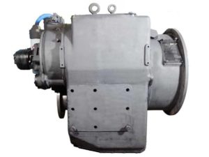
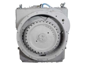
Installing the Twin Disc MG-540 marine gear is a precision-driven task that requires adherence to alignment protocols, torque specifications, and hydraulic preparation. Whether integrating the gear into a new vessel or replacing an existing transmission, this section ensures your installation meets OEM-grade reliability while preventing early failures due to misalignment, torque distortion, or contamination.
This expanded guide covers:
- Engine and transmission alignment using SAE standards
- Gear ratio validation
- Final torque specifications for housings and fasteners
- Installation of critical service components like filters, breathers, and dipsticks
Alignment References (SAE J-1033 and J-617) For Twin Disc MG-540 Marine Gear
Proper shaft alignment is the most important mechanical task during the installation of any marine gear — especially one as heavy-duty and high-output as the Twin Disc MG-540. Misalignment introduces side-loading on shafts and bearings, leading to rapid wear and eventual failure of input/output components.
SAE J-1033 Alignment Standard
SAE J-1033 governs the in-line alignment of marine engines and transmissions. It specifies allowable runout and concentricity values for coupled shafts. The goal is to ensure that the engine flywheel housing and the transmission input flange share a common centerline.
Key Requirements under SAE J-1033:
- Total Indicator Runout (TIR) for flywheel pilot bore: ≤ 0.005 inches
- TIR for flywheel housing face: ≤ 0.002 inches
- Misalignment between shaft centers: ≤ 0.005 inches per foot of shaft length
Use a dial indicator mounted on the transmission input coupling to measure runout against the engine flywheel housing. Rotate the engine 360° and record measurements at 90° intervals.
SAE J-617 Flywheel Housing Compatibility
SAE J-617 specifies the mounting interface for the engine flywheel housing and marine transmission bell housing. The MG-540 typically mates to SAE No. 1 or SAE No. 0 housings depending on the application and BOM configuration.
Checklist for SAE J-617 Interface:
- Confirm that pilot bore and bolt circle dimensions match
- Use the correct flange adapter plate (if required by engine model)
- Tighten all mating bolts to specification (see torque chart below)
Installation Best Practice:
- Use a centering pilot tool to align the transmission input shaft before tightening bell housing bolts
- Rotate the flywheel during tightening to ensure smooth engagement of splines
Gear Ratio Measurement For Twin Disc MG-540 Marine Gear
Before startup, it’s critical to verify that the installed MG-540 unit has the correct gear ratio for the vessel’s propulsion requirements. This ensures compatibility between engine torque curve, propeller design, and maneuvering performance.
How to Measure Gear Ratio (Manually)
- Mark the input coupling and output flange.
- Rotate the input shaft using a breaker bar or hand lever and count the number of full turns required to make the output shaft complete one full revolution.
- Use the formula:
Gear Ratio=Input Shaft RotationsOutput Shaft Rotations\text{Gear Ratio} = \frac{\text{Input Shaft Rotations}}{\text{Output Shaft Rotations}}Gear Ratio=Output Shaft RotationsInput Shaft Rotations
Example: If the input shaft rotates 3.91 times while the output shaft rotates once, the gear ratio is 3.91:1
- Compare the result to the transmission’s nameplate, which lists the exact gear ratio by BOM (Bill of Materials) number.
When to Measure Gear Ratio
- When installing a replacement or rebuilt MG-540
- When there is uncertainty about prior repairs
- As part of pre-commissioning QA on multi-vessel fleets
Common MG-540 Gear Ratios
- 1.71:1
- 1.93:1
- 2.58:1
- 2.90:1
- 3.26:1
- 3.91:1
- 4.10:1
- 4.60:1
- 5.17:1
- 6.18:1
- 7.00:1
- 7.47:1
Matching the correct ratio to the vessel’s propeller specifications is key to efficient propulsion and fuel economy.
Final Torque Settings for Housing and Top/Bottom Covers For Twin Disc MG-540 Marine Gear
Proper torque application ensures consistent clamping force, prevents warping, and secures gasket integrity across the MG-540 housing and covers. Uneven or excessive torque can result in oil leaks, casting stress, or distorted sealing surfaces.
Torque Wrench Use Guidelines
- Use calibrated torque wrenches
- Apply light oil on fastener threads unless otherwise specified
- Torque in a crisscross sequence, particularly for covers and retainers
- Record and verify torque values on a checklist
Housing and Cover Torque Specifications
| Component | Bolt Size | Torque Specification |
| Top Cover | 1/2-13 x 1.5 | 65 lb-ft |
| Bottom Cover | 1/2-13 x 1.5 | 65 lb-ft |
| Bearing Retainers | 1/2-13 | 65 lb-ft |
| Input Shaft Seal Housing | 3/8-16 | 30 lb-ft |
| Rear Manifold Cover | 1/2-13 | 90 lb-ft |
| Output Shaft Clamp Plate | 1-14 x 2 | 140 lb-ft |
| Internal Clutch Fasteners | 1/2-13 x 6 | 90 lb-ft |
Important: Always recheck torque 24 hours after first heat cycle of the engine to allow for thermal settling.
Thread Lockers
- Use Loctite 242 (Blue) for removable assemblies like valve covers and seals
- Use Loctite 271 (Red) for permanent assemblies like internal shafts and flange bolts
- Avoid over-applying thread locker to prevent hydraulic lock in blind holes
Installation of Filters, Breather, and Oil Level Gauge For Twin Disc MG-540 Marine Gear
The final step in installation involves preparing the MG-540 for fluid circulation and safe startup by installing and configuring its filtration and lubrication monitoring systems.
Filter Installation
The MG-540 uses both a main oil pressure filter and lubrication suction strainers:
Main Filter:
- Part Number: 1016052 (Spin-on type)
- Installation Steps:
- Apply a film of clean oil to the gasket
- Screw filter onto mount and hand-tighten
- After first startup, check for leaks and re-torque if necessary
Suction Strainers:
- Located in left and right cover assemblies
- Clean or replace every 100 hours
- Secure with 3/8-16 bolts torqued to 25 lb-ft
Breather Installation
The MG-540 is equipped with a breather assembly to prevent pressure buildup and allow for thermal expansion.
Steps:
- Insert breather into top cover opening
- Torque to 15–20 lb-ft
- Confirm air flow with light pressure (should not be fully sealed)
Warning: Do not plug breather — doing so can lead to seal failure under pressure
Oil Level Gauge (Dipstick) Installation
The oil level gauge is crucial for maintaining proper fluid balance in the MG-540, which has a nominal capacity of 32 quarts.
Steps:
- Insert dipstick tube into side-mounted housing port
- Align with mounting bracket and secure with 5/16-18 bolt
- Insert dipstick and verify:
- Engine OFF
- Transmission at operating temperature
- Level between “FULL” and “ADD” marks
- Record oil type used (SAE 30/40 mineral or approved hydraulic oil)
Pro Tip: Label the dipstick with oil type and last service date using an industrial-grade tag
Final Installation Checklist
Before startup, verify each task on this checklist:
| System Area | Task | Verified |
| Alignment | Dial indicator reads ≤ 0.005″ TIR | ✅ |
| Gear Ratio | Measured input/output rotation matches nameplate | ✅ |
| Fasteners | All torqued to correct specs with torque wrench | ✅ |
| Seals & Gaskets | All replaced and lightly oiled | ✅ |
| Filters | Spin-on and strainers installed and torqued | ✅ |
| Breather | Installed and confirmed open | ✅ |
| Dipstick & Oil Level | Installed, correct reading with engine off | ✅ |
| Wiring (if applicable) | EC050 or solenoids connected and test pulsed | ✅ |
| Cooling Lines | Connected to heat exchanger and leak-checked | ✅ |
Summary
Installing the Twin Disc MG-540 marine gear correctly is critical to achieving smooth propulsion performance, avoiding leaks, and ensuring long-term drivetrain health. By strictly adhering to SAE alignment standards, torque specs, and gear verification procedures, you ensure this heavy-duty transmission operates as reliably at sea as it does on paper.
Videos About Twin Disc Transmissions
6 Reasons Your Twin Disc Transmission Has Low Oil Pressure
7 Reasons Your Twin Disc Transmission Is Overheating
3 Reasons Your Clutch Plates in Your Twin Disc Transmission Are Making Excessive Noise
Bull Gear On A Twin Disc Transmission
Rebuilt Twin Disc Transmissions