

 Free US Calls: 1-888-433-4735
 International: 305-545-5588
Installing the Twin Disc MG509 marine gear requires precision, attention to detail, and adherence to best practices to ensure optimal performance and longevity. Correct installation is essential to maximize operational efficiency, prevent premature wear, and minimize potential failures during operation. This comprehensive guide outlines the critical steps, including the pre-installation checklist, mounting and alignment instructions, and lubrication requirements to ensure a seamless installation process.
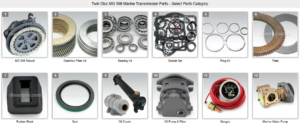
Parts Catalog for Twin Disc MG509 Marine Transmissions
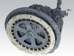
Rebuilt Twin Disc MG509 Marine Transmissions
Bearings For Twin Disc MG509 Marine Transmissions
Plate Kit For Twin Disc MG509 Marine Transmission
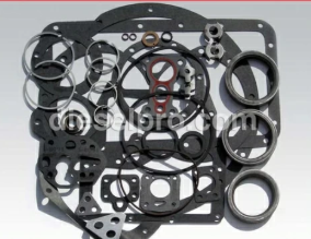
Gasket Kits For Twin Disc MG509 Marine Transmission
Pre-Installation Checklist for Twin Disc MG509 Marine Gear
Before beginning the installation process, it is essential to complete a thorough pre-installation checklist. Proper preparation helps identify potential issues early, ensures the availability of necessary tools and materials, and guarantees a smoother and more efficient installation.
1. Verify Product Specifications
- Confirm Model and Configuration: Ensure that the MG509 unit matches the required model, gear ratio, and configuration for the specific marine application.
- Review Technical Documentation: Refer to the service manual for detailed technical specifications, torque values, and installation diagrams.
- Inspect Serial Numbers: Check the serial numbers and ensure they match the installation records for future tracking and maintenance.
2. Inspect the Marine Gear for Damage
- Visual Inspection: Carefully examine the MG509 for any visible signs of damage, such as cracks, corrosion, or wear on critical components like mounting surfaces, flanges, and gear teeth.
- Check for Missing Components: Verify that all parts, including bolts, seals, gaskets, and hydraulic components, are present and in good condition.
- Inspect the Packaging: If the unit was shipped, inspect the packaging for any signs of mishandling that may have resulted in concealed damage.
3. Prepare the Installation Area
- Ensure Cleanliness: The installation area should be clean and free from debris, dust, and contaminants that could interfere with the alignment or mounting.
- Adequate Lighting and Ventilation: Ensure that the workspace is well-lit and ventilated to provide a safe and efficient working environment.
- Safety Precautions: Confirm that safety equipment, such as gloves, eye protection, and appropriate lifting gear, is available and in good condition.
4. Confirm Compatibility with Engine and Mounts
- Check Engine Mounts: Ensure the engine mounts are compatible with the MG509 and are in good condition. Replace worn or damaged mounts as needed.
- Verify Mounting Surface: Confirm that the mounting surface is flat, level, and free from defects to ensure proper alignment.
- Inspect Coupling Components: Ensure that coupling components, such as flanges and shafts, are compatible and free from damage.
5. Gather Necessary Tools and Equipment
- Lifting Equipment: Prepare hoists, cranes, or forklifts capable of safely lifting and positioning the MG509, considering its weight.
- Alignment Tools: Ensure availability of dial indicators, straight edges, and feeler gauges for precision alignment.
- Torque Wrenches: Prepare torque wrenches calibrated to the required specifications to ensure correct bolt tightening.
- Lubrication Tools: Gather oil, grease, and lubrication tools for pre-lubricating critical components.
6. Verify Fluid Levels and Conditions
- Check Lubricant Levels: Verify that initial lubrication levels meet manufacturer recommendations for installation.
- Inspect Seals and Gaskets: Ensure seals are properly seated and gaskets are free from damage to prevent leaks during initial operation.
7. Safety and Environmental Compliance
- Review Safety Guidelines: Familiarize the installation team with safety procedures, including how to handle heavy machinery and potential hazards.
- Prepare Spill Kits: Have spill containment materials on hand in case of oil or lubricant spills.
Mounting and Alignment Instructions for Twin Disc MG509
Correct mounting and alignment are critical to ensure the MG509 operates smoothly and efficiently. Improper alignment can lead to excessive wear, vibrations, noise, and even catastrophic failure. The following steps guide the precise installation and alignment of the MG509.
1. Positioning the Transmission
- Use Proper Lifting Equipment: Attach lifting gear to designated lifting points on the MG509 to avoid damage. Ensure that lifting equipment can safely handle the weight of the unit.
- Lower Carefully: Lower the MG509 into position slowly and carefully to avoid misalignment or damage to the mounting surfaces.
- Preliminary Position Check: Position the MG509 so that it aligns with the engine coupling and propeller shaft.
2. Mounting the Transmission
- Verify Mounting Holes: Ensure that the mounting holes on the engine and transmission align correctly.
- Insert Mounting Bolts: Insert bolts into the mounting holes and hand-tighten them initially to allow for final adjustments.
- Check for Flatness: Use a straight edge to confirm that the mounting surfaces are flat and flush, ensuring even load distribution.
- Torque to Specification: Once correctly positioned, tighten the bolts incrementally in a crisscross pattern to the manufacturer’s torque specifications.
3. Shaft Alignment Procedures
Proper shaft alignment between the MG509 and the engine is essential to minimize vibration and wear.
- Measure Angular Alignment: Use a dial indicator or feeler gauge to check the angular alignment between the coupling flanges. Tolerances should be within 0.002 inches to ensure smooth operation.
- Measure Parallel Alignment: Use straight edges to check that the flanges are parallel, with minimal deviation. Misalignment can lead to vibration and excessive wear on bearings and seals.
- Adjust as Necessary: If alignment is out of tolerance, adjust the engine or transmission mounts accordingly to bring it into alignment.
- Recheck Alignment: After adjustments, recheck alignment measurements to confirm accuracy.
4. Coupling and Flange Connection
- Clean the Flanges: Ensure coupling flanges are clean and free of debris before connecting.
- Use Anti-Seize Compound: Apply anti-seize compound to the bolts to facilitate easy removal during future maintenance.
- Bolt Connection: Connect the flanges using bolts and tighten them incrementally to specified torque values.
- Verify Free Movement: Rotate the propeller shaft by hand to ensure smooth, free movement without binding.
5. Final Mounting Inspection
- Visual Inspection: Conduct a thorough visual inspection to ensure all bolts are secure and aligned.
- Check for Movement: Gently rock the transmission to confirm it is securely mounted without excessive play.
- Document Settings: Record alignment measurements and torque settings for future reference.
Lubrication Requirements During Installation
Proper lubrication is critical during the installation of the MG509 to ensure smooth operation from the first start-up. Lubrication reduces friction, minimizes heat buildup, and protects against wear.
1. Initial Lubrication Application
- Apply Pre-Lubrication: Lubricate key components, including gears, bearings, and seals, with manufacturer-recommended lubricants prior to initial operation.
- Fill Lubrication Reservoirs: Ensure that oil reservoirs are filled to the recommended levels. For the MG509, the oil capacity typically ranges from 3 to 5 gallons, depending on configuration.
- Prime the Lubrication System: Run the lubrication pump (if available) to circulate oil throughout the transmission and remove air pockets.
2. Verify Oil Quality and Levels
- Inspect Oil Quality: Use only marine-grade lubricants with the correct viscosity (e.g., SAE 30 or 40).
- Monitor for Leaks: After initial filling, inspect for leaks around seals and gaskets. Tighten any fittings as necessary.
- Check for Air Locks: Ensure there are no air pockets within the system that could restrict oil flow.
3. Perform Initial Run-In Procedure
- Start the Engine at Low RPM: Operate the engine at low RPMs initially to allow oil to circulate fully within the transmission.
- Monitor Oil Pressure: Check the oil pressure to confirm it meets the manufacturer’s specifications, typically between 30 to 60 psi.
- Check for Abnormalities: Listen for unusual noises and check for leaks. If issues are detected, shut down and inspect before proceeding.
4. Post-Installation Oil Check
- Inspect Oil Levels Again: After the initial run, recheck oil levels and top up if necessary.
- Replace Oil Filter: If the oil filter was not replaced before installation, install a new filter to ensure optimal oil flow.
Summary
Proper installation of the Twin Disc MG509 marine gear is essential for achieving optimal performance, reducing wear, and extending the operational lifespan. By following the detailed pre-installation checklist, performing precise mounting and alignment, and ensuring accurate lubrication requirements, marine operators can set their equipment up for long-term success.
Disclaimer: For more detailed technical information and specific servicing procedures, always refer to the official Twin Disc MG509 service manual.
Rebuilt Twin Disc MG509 Marine Transmissions
Bearings For Twin Disc MG509 Marine Transmissions
Plate Kit For Twin Disc MG509 Marine Transmission
Gasket Kits For Twin Disc MG509 Marine Transmission
Videos About Twin Disc Transmissions
6 Reasons Your Twin Disc Transmission Has Low Oil Pressure
7 Reasons Your Twin Disc Transmission Is Overheating
3 Reasons Your Clutch Plates in Your Twin Disc Transmission Are Making Excessive Noise
Bull Gear On A Twin Disc Transmission
Rebuilt Twin Disc Transmissions