

 Free US Calls: 1-888-433-4735
 International: 305-545-5588
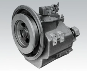
Parts Catalog for Twin Disc MG5091 Marine Transmissions
Rebuilt Twin Disc MG5091 Marine Transmissions
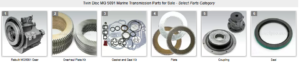
Plate Kit For Twin Disc MG5091 Marine Transmission
Gasket Kits For Twin Disc MG5091 Marine Transmission
Correct installation of the Twin Disc MG-5091 Marine Gear is critical for the long-term performance, reliability, and safety of your marine propulsion system. Whether installing a new unit, replacing an old one, or reinstalling after service, taking shortcuts during the installation process can lead to misalignment, shaft damage, premature clutch wear, or complete transmission failure. This guide provides a thorough, step-by-step process to ensure a smooth, safe, and precise installation.
We’ll begin by outlining pre-installation inspection protocols, including checks of the mounting flange, engine flywheel alignment, and shaft runout. Then, we’ll walk through the full installation process, covering soft foot correction, coupling alignment, and bolt torque specifications. These procedures are based on best practices from the marine industry and should be followed by any mechanic, technician, or vessel operator working with the MG-5091.
Pre-Installation Inspection for Twin Disc MG-5091 Marine Gear
Before any physical installation begins, it’s crucial to inspect the mounting surfaces, shafts, and coupling components. A thorough inspection can prevent installation errors that could later result in vibration, oil leaks, or even catastrophic damage to your marine gear system.
Mounting Flange Condition
The mounting flange of the MG-5091 connects to the engine’s bellhousing. It must be flat, clean, and free of any imperfections that could interfere with alignment or secure mating.
Inspection Steps:
- Visual Check
- Look for gouges, burrs, scratches, or corrosion on the transmission’s mounting face.
- Inspect dowel pin holes and mounting bolt holes for elongation or deformation.
- Clean the Surface
- Wipe with solvent and a lint-free cloth to remove oil or debris.
- Use a fine stone or emery cloth to remove high spots without removing material.
- Flatness Verification
- Use a precision straightedge and feeler gauges.
- Maximum allowable deviation: typically 0.002 inches per foot of flange surface.
- Thread Condition
- Inspect mounting bolt holes for stripped threads or contamination.
- Use a thread chaser if needed, and clean out debris with compressed air.
A distorted or damaged flange can cause improper gear mesh, lead to excessive vibration, and shorten the life of both the transmission and the engine.
Alignment Checks
Proper alignment between the engine and transmission is one of the most important steps in installation. Misalignment can damage input bearings, create excessive vibration, and stress the engine crankshaft and gearbox shaft.
Types of Alignment:
- Angular Alignment: Ensures the mating surfaces (bellhousing and gearbox flange) are parallel.
- Offset Alignment: Ensures the gearbox centerline matches the engine crankshaft centerline.
How to Check:
- Mount a dial indicator on the bellhousing and rotate the crankshaft to measure face runout and bore runout.
- Maximum allowable face runout: 0.005 inches
- Maximum allowable bore runout: 0.003 inches
Corrective Action:
Use precision shims or correct soft foot conditions (discussed below) to adjust alignment. Do not attempt to “force” the gearbox into place with bolts.
Shaft Runout Inspection
Output shaft runout refers to the amount of radial or axial movement as the shaft rotates. Excessive runout can lead to seal leaks, vibration, and coupling wear.
Inspection Process:
- Mount a dial indicator on a rigid base, with the tip contacting the output flange surface.
- Rotate the shaft slowly by hand.
- Record total indicated runout (TIR) on both radial and axial planes.
Acceptable TIR Limits:
- Radial runout: 0.002–0.005 inches
- Axial (endplay): Typically 0.003–0.006 inches, depending on model
If runout exceeds limits:
- Inspect the coupling for damage or contamination
- Check for bent shafts or damaged bearings
- Verify that the transmission is not sitting unevenly on the mounts
Alignment and Mounting for Twin Disc MG-5091 Marine Gear
Once the pre-installation checks are complete and the gearbox has passed all inspections, you can begin the alignment and mounting process. This section outlines how to correct soft foot conditions, align the coupling, and torque all mounting hardware to factory specifications.
Soft Foot Correction
Soft foot occurs when one or more transmission mounting pads do not sit flat on the engine bed or stringers. This results in uneven loading, misalignment, and dynamic stress during operation.
How to Detect Soft Foot:
- Place feeler gauges under each of the four gearbox mounting pads.
- Tighten three of the four bolts, leaving one loose, then check the gap under the loose pad.
- Swap the loose bolt position and repeat the check for all four corners.
If the gap is greater than 0.003 inches, soft foot is present.
Correcting Soft Foot:
- Use stainless steel shims (never washers) under the affected mounting point.
- Recheck with feeler gauges after shimming.
- Torque the bolts lightly and check again to confirm proper seating.
- If excessive soft foot persists, check for twisted engine rails or mounting surfaces.
Even a small soft foot condition can result in bearing fatigue and shaft misalignment under load. Always address it before proceeding with full bolt torque.
Coupling Alignment Methods
The MG-5091 output shaft is connected to the vessel’s propeller shaft using a mechanical coupling. Improper alignment between the gearbox and the propeller shaft is one of the leading causes of shaft seal failure and excessive vibration.
There are two key forms of coupling alignment: angular alignment and parallel alignment.
Angular Alignment (Face Alignment)
This ensures the flanges of the gearbox and shaft coupling are parallel.
Tools Required:
- Feeler gauges
- Machinist’s square or straightedge
Procedure:
- Separate the coupling flanges slightly (leave ~0.015″ gap).
- Insert feeler gauges at 12, 3, 6, and 9 o’clock positions.
- Record any differences in gap.
Maximum tolerance: ≤ 0.002–0.004 inches depending on RPM and shaft length.
Parallel Alignment (Rim Alignment)
This ensures the flanges are concentric—centerlines match.
Tools Required:
- Dial indicator mounted to one flange
- Rotate flange to read indicator at 4 points
Maximum Runout Tolerance:
- ≤ 0.003 inches TIR for most marine applications
- For long shafts or high-speed vessels, ≤ 0.001 inches may be required
Correcting Misalignment:
- Adjust shims at the gearbox mounting feet.
- For large deviations, check engine mounts as well.
- Tighten bolts progressively and re-check alignment after torqueing.
Recheck alignment after running the engine to temperature, as heat may expand components and affect alignment.
Bolt Torque Specifications for Twin Disc MG-5091 Marine Gear
Proper torque on all mounting and coupling bolts is essential. Under-torquing can cause bolts to loosen, while over-torquing can strip threads or warp the flange.
General Bolt Torque Guidelines
| Bolt Size (Grade 8.8) | Torque (Ft-lbs) | Application |
| 3/8″ – 16 | 30–35 | Small covers, sensors |
| 7/16″ – 14 | 50–55 | Cooler mounts |
| 1/2″ – 13 | 75–85 | Mounting bolts |
| 5/8″ – 11 | 125–135 | Output flange |
| 3/4″ – 10 | 200–220 | Bellhousing bolts |
Use a calibrated torque wrench and tighten in a crisscross pattern to evenly distribute load.
Bellhousing Bolt Torque
- Torque gradually in three stages (30%, 60%, 100%)
- Start at 40 ft-lbs → 65 ft-lbs → 85 ft-lbs for 1/2″ bolts
- Final check all bolts after engine has run at operating temp
Mounting Bolt Torque Sequence
- Align gearbox with engine and shaft
- Install all four feet bolts loosely
- Perform soft foot check and shim as required
- Tighten in cross pattern to 50% torque
- Final torque all to spec (usually 85 ft-lbs for 1/2″ bolts)
Output Coupling Torque
- Always use new lock washers or thread locker
- Do not reuse deformed or stretched coupling bolts
- Torque evenly in sequence, and recheck after sea trial
Post-Installation Checks
After the MG-5091 is installed, aligned, and torqued to specification, perform a full checklist of system verifications before starting the engine.
Checklist:
✅ Confirm engine and transmission are aligned within 0.002–0.004 inches
✅ All mounting bolts torqued to spec
✅ Soft foot verified and corrected
✅ Coupling alignment completed and recorded
✅ Output flange bolts installed and torqued
✅ Oil level at correct fill line
✅ Cooling system lines connected and bled
✅ Hydraulic control lines secured
✅ Vent and breather installed and unobstructed
✅ Transmission in neutral position
✅ Lockout/tagout tags removed (post-check)
First Startup Notes:
- Monitor oil pressure during the first run (ensure it’s within service range)
- Check for leaks at shaft seals and cooling lines
- Listen for unusual noise or vibration
- Recheck alignment after first engine warm-up
- Retorque mounting and coupling bolts after 2–3 hours of operation
Summary
Installation Procedures for Twin Disc MG-5091 Marine Gear
Installing the Twin Disc MG-5091 Marine Gear is not simply about placing a gearbox into a compartment—it is a precision task requiring alignment expertise, torque accuracy, and detailed inspection protocols. Done correctly, it ensures thousands of hours of reliable service in tough marine environments. Done incorrectly, it can result in misalignment, failure, or costly vessel downtime.
Installation Best Practices Recap:
- Inspect flange surfaces, shafts, and alignment before installing.
- Always correct soft foot before final bolt torque.
- Perform accurate coupling alignment using dial indicators or feeler gauges.
- Follow torque specs exactly using a calibrated wrench.
- Run a full post-installation checklist before starting the engine.
A successful installation lays the foundation for long-term transmission performance and helps prevent issues like clutch slippage, bearing wear, and vibration-induced failures.
Rebuilt Twin Disc MG5091 Marine Transmissions
Plate Kit For Twin Disc MG5091 Marine Transmission
Gasket Kits For Twin Disc MG5091 Marine Transmission
Videos About Twin Disc Transmissions
6 Reasons Your Twin Disc Transmission Has Low Oil Pressure
7 Reasons Your Twin Disc Transmission Is Overheating
3 Reasons Your Clutch Plates in Your Twin Disc Transmission Are Making Excessive Noise
Bull Gear On A Twin Disc Transmission
Rebuilt Twin Disc Transmissions