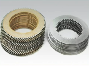
Parts catalog for Twin Disc MG50590A Marine Transmissions
Overhaul Plate Kit For Twin Disc MG5090A Marine Transmission
Gasket Kits For Twin Disc MG5090A Marine Transmission
Introduction: Why Control Systems Matter for the MG-5090A Marine Transmission
The Twin Disc MG-5090A marine transmission is a reliable and high-performing hydraulic gear, but like any transmission, it depends heavily on precise control inputs to operate correctly. Whether you’re using manual mechanical linkages or an electronic control system such as the Twin Disc EC300, it’s vital that these systems be correctly adjusted, smoothly operating, and free from wear.
Failure to inspect and maintain the control system can lead to symptoms that mimic internal transmission failure, such as:
- Slipping or harsh shifting
- Delayed engagement
- Stuck in gear
- Inability to shift between forward and reverse
This comprehensive guide will walk you through how to inspect, test, lubricate, and adjust both mechanical and electronic control systems, as well as explain the role of each part and provide troubleshooting tips. This is essential reading for marine mechanics, vessel owners, and service managers responsible for keeping their MG-5090A-equipped vessels running smoothly.
Control System Overview for Twin Disc MG-5090A Marine Gear
Mechanical vs. Electronic Control Systems
The MG-5090A can be operated via:
- Mechanical cable-actuated systems, using traditional Morse-style shift levers and linkage arms
- Electronic control systems, such as the Twin Disc EC300, which convert lever motion to electronic signals that actuate solenoids or motors
Each system has different maintenance requirements, but both must achieve full travel of the clutch valve lever (also known as the control lever or shift lever on the transmission).
Function of the Control Lever
The clutch control lever on the MG-5090A:
- Directs oil pressure to either the forward or reverse clutch pack
- Interfaces with either a mechanical cable or actuator motor
- Has detent positions for forward, neutral, and reverse
- Must move fully into each position to ensure complete clutch engagement
Improper lever movement, resistance, or misalignment can result in partial engagement, leading to slippage and increased wear on the clutch components.
Visual Inspection of Mechanical Linkages
Step 1: Identify All Linkage Components
On a mechanical system, identify and inspect the following:
- Shift lever at helm
- Push-pull control cable
- Cable mounts at helm and transmission
- Transmission-side lever arm
- Clevis pins and bushings
- Detent mechanism (spring and ball assembly on gear housing)
Step 2: Disconnect and Test Lever Movement by Hand
- Disconnect the shift cable from the transmission lever
- Manually move the clutch lever through forward, neutral, and reverse
You should feel:
- Smooth movement
- Firm detents (clicks) at each gear position
- No grinding, catching, or binding
If resistance is felt, lubricate pivot points and inspect for corrosion, bent hardware, or cracked brackets.
Step 3: Inspect Cable for Wear and Binding
- Run the control lever at the helm through full range of motion
- Observe the cable housing and mounting clamps
- Check that cable doesn’t bend excessively, kink, or chafe on adjacent components
Signs of a failing cable:
- Excessive play in lever
- Cable feels spongy or stiff
- Delay between lever movement and clutch response
- Visible rust or broken strands in the cable jacket
Correction: Replace the cable with a marine-grade stainless core cable of the same length and travel range.
Step 4: Lubricate the Mechanical Linkage
Use marine-grade lithium grease or water-resistant anti-seize lubricant on:
- Clevis pins
- Pivot joints
- Detent lever spring area (if accessible)
- Helm lever linkage joints
Do not lubricate the inside of the cable sheath unless it’s a serviceable type. Many modern cables are sealed and designed to operate dry.
Checking and Adjusting Lever Travel
Step 1: Verify Full Lever Travel
From neutral, push the helm lever into forward and reverse, and observe if the clutch lever on the MG-5090A fully moves into its respective detent.
If the lever fails to:
- Reach the detent stop
- Return to center reliably
- Stay positively in gear
…it could result in partial clutch engagement, causing slippage and heat buildup.
Step 2: Adjust Cable Endpoints
On both the helm and transmission ends:
- Loosen the cable clamps
- Reposition the cable anchor so the lever reaches full travel
- Confirm the neutral detent aligns with the control lever’s center point
- Retighten and test
Cable travel should be:
- Approximately 2.5 inches for most shift arms
- Aligned so the detents click firmly into place
Step 3: Inspect Control Brackets and Bushings
Over time, transmission-mounted control brackets and shift arm bushings may develop:
- Elongated holes
- Cracks or fatigue
- Worn bushings, causing lever slop
- Loose bolts that allow lever misalignment
Replace damaged brackets and re-torque mounting bolts to factory specification to prevent movement under load.
Electronic Control System Checks (e.g., Twin Disc EC300)
Step 1: Run System Diagnostics
Modern control systems like the EC300 have built-in diagnostic tools, which can be accessed via:
- Display module (LCD screen)
- Laptop interface
- LED light codes on actuator
Diagnostic Functions May Include:
- Actuator response test
- Position sensor calibration
- Error code history
- Voltage input/output verification
Step 2: Observe Shifting Behavior
With the vessel powered but engine off:
- Move the shift lever at the helm
- Watch the actuator on the transmission move the clutch lever
- Confirm full travel into forward and reverse detents
Signs of actuator failure or miscalibration:
- Incomplete movement of the clutch lever
- Slow or jerky response
- Lever returns to neutral unexpectedly
- Actuator emits clicking or grinding noises
Step 3: Calibrate Shift Points
Use the manufacturer’s calibration procedure to:
- Set the neutral, forward, and reverse limits
- Program the shift delay (optional)
- Adjust actuator travel to match the MG-5090A’s lever arc
Important: Misaligned shift limits will result in incomplete clutch engagement—even if the lever appears to be in gear.
Step 4: Check Electrical Connections
Inspect:
- Power and ground terminals at the actuator
- CANbus or harness connectors
- Signs of corrosion or pin misalignment
Use dielectric grease to prevent future moisture ingress.
Detent Mechanism Inspection and Adjustment
The MG-5090A features an internal detent mechanism, often located at the base of the clutch valve lever, consisting of:
- Spring
- Steel ball or roller
- Detent plate
This provides a tactile “click” at gear positions and helps hold the transmission in gear even if the cable tension fluctuates.
Step 1: Inspect Detent Action
With the transmission off and lever disconnected:
- Move the clutch lever slowly
- Feel for 3 distinct detents: forward, neutral, and reverse
Step 2: Troubleshoot Weak Detent
If detents feel soft or missing:
- The detent spring may be worn or broken
- Debris may be obstructing the detent track
- Internal corrosion could be present
Fix: Remove the clutch lever cover (if accessible) and inspect the spring-ball detent. Replace worn components with a detent repair kit from Diesel Pro Power.
Step 3: Verify Hold Strength
Shift into gear and attempt to gently nudge the lever. It should not slip out of gear unless pulled manually with force.
Final Test and Adjustment Checklist
Once all mechanical or electronic components are verified, conduct a full operational test.
Mechanical System Test:
- Move helm lever through full range
- Confirm cable does not bind or flex excessively
- Verify full clutch lever travel at the transmission
- Confirm firm detents at forward, neutral, and reverse
- Shift under engine power and test response
- Inspect for slippage, delays, or vibration
Electronic System Test:
- Perform full system calibration
- Verify shift lever inputs match actuator response
- Listen for any actuator hesitation
- Confirm visual detent alignment on the MG-5090A
- Shift under engine power and observe oil pressure (250–300 PSI is ideal)
Final Adjustments:
- Adjust cable clamps, actuator stops, or lever brackets as needed
- Tighten all hardware to torque specs
- Apply marine-grade grease to all moving joints
- Record shift lever position and system status in your logbook
Troubleshooting Control System Symptoms
| Symptom | Likely Cause | Recommended Action |
| Transmission won’t shift | Cable failure / actuator fault | Replace cable or inspect EC300 wiring |
| Slipping despite oil pressure OK | Lever not reaching detent | Adjust cable endpoints or recalibrate ECU |
| Lever returns to neutral | Weak detent mechanism | Inspect and replace spring/ball |
| Shudder during shift | Partial clutch engagement | Confirm full lever travel and clutch inspection |
| Harsh shifting (electronic) | Incorrect actuator timing | Recalibrate EC300 or update firmware |
Pro Tips to Prevent Control Issues on the MG-5090A
- Grease linkages every 6 months or more frequently in saltwater use
- Check cable mounting brackets for movement at every oil change
- Replace cables every 3–5 years regardless of appearance
- Keep EC300 software updated and record calibration settings
- Never force the lever—stiffness indicates a problem needing correction
Diesel Pro Power Control Support and Replacement Parts
At Diesel Pro Power, we supply:
- Twin Disc MG-5090A control levers
- Replacement detent kits
- Shift cables (standard and custom lengths)
- EC300-compatible actuators
- Bushing kits and bracket assemblies
- Rebuilt MG-5090A transmissions with pre-calibrated controls
We also provide expert guidance on mechanical-to-electronic conversion, system calibration, and complete transmission rebuilds.
Summary: Control Systems = Transmission Health on the MG-5090A
The clutch packs and gears inside your Twin Disc MG-5090A are engineered for durability, but they only function correctly if the control system delivers the right signals—mechanically or electronically. Improper cable routing, misaligned shift arms, weak detents, or actuator calibration issues can all lead to symptoms that appear to be transmission failures but are actually external control problems.
Proper linkage and control inspection is an essential part of your MG-5090A’s annual maintenance schedule—and one of the easiest ways to prevent costly misdiagnoses and premature wear.
Quick Reference Inspection Chart
Component |
Check Frequency |
Inspection Criteria |
| Mechanical shift cable | Every 6 months | No binding, full travel, no corrosion |
| Lever travel and detents | Every 1,000 hours | Positive stops at FWD/NEUTRAL/REV |
| Brackets and bushings | Every oil change | No cracks, proper alignment |
| EC300 actuator calibration | Annually or after repair | Full travel, correct gear assignment |
| Grease pivot points | Every 6 months | No dry or corroded joints |
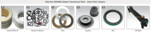
Overhaul Plate Kit For Twin Disc MG5090A Marine Transmission
Gasket Kits For Twin Disc MG5090A Marine Transmission
Videos About Twin Disc Transmissions
6 Reasons Your Twin Disc Transmission Has Low Oil Pressure
7 Reasons Your Twin Disc Transmission Is Overheating
3 Reasons Your Clutch Plates in Your Twin Disc Transmission Are Making Excessive Noise
Bull Gear On A Twin Disc Transmission
Rebuilt Twin Disc Transmissions