

 Free US Calls: 1-888-433-4735
 International: 305-545-5588
The lubrication system in Detroit Diesel Series 60 engines is critical for reducing friction, maintaining optimal operating temperatures, and ensuring the longevity of engine components. The system operates by distributing oil to the engine’s moving parts, which include bearings, pistons, and gears, through a network of galleries, pumps, and filters.
Parts Catalog for 11.1L Detroit Diesel 60 Series Marine Engine
Parts Catalog for 12.7L Detroit Diesel 60 Series Marine Engine
Parts Catalog for 14L Detroit Diesel 60 Series Marine Engine
Key Components and Flow of the Lubrication System
Key components of this system include:
- Oil Pump
- Pressure Regulator Valve
- Pressure Relief Valve
- Oil Filters
- Oil Cooler
- Oil Level Dipstick
- Oil Pan
- Ventilation System
- Bypass Filter (optional)
These components work together to ensure that every moving part within the engine receives an uninterrupted supply of clean, pressurized oil, helping to reduce friction, carry away heat, and prevent component wear.
The schematic flow of oil starts at the pump, proceeds through filters and coolers, and ends with the oil’s return to the pan after circulating through the engine’s lubrication points. The system is designed to maintain optimal oil pressure and temperature, ensuring engine reliability even under extreme load or temperature conditions.
Schematic of Lubrication Flow
Oil is drawn from the sump or oil pan by the gear-driven oil pump and is immediately pressurized. It is then directed through full-flow oil filters that remove contaminants, and in some configurations, an additional bypass filter captures finer particulates. The filtered oil continues to the oil cooler, which helps regulate oil temperature to prevent thermal breakdown and maintain viscosity.
Once cooled, the oil enters the main galleries of the engine block, where it is distributed to critical areas including:
- Camshaft Bearings – to reduce friction at the cam lobes and journals.
- Crankshaft Bearings – to provide a high-pressure oil film for the rotating crankshaft.
- Rocker Arms and Valve Train – ensuring smooth valve actuation.
- Turbocharger Bearings – protecting the high-speed rotating assembly from thermal stress and wear.
- Pistons and Cylinder Walls – providing splash lubrication and aiding in heat dissipation.
Any bypassed oil, overflow from the regulator, or oil that has completed its lubrication circuit is routed back to the sump. This closed-loop system ensures continuous lubrication throughout engine operation, with real-time regulation via pressure relief valves and pressure sensors to prevent over-pressurization or starvation.
Components and Functions
Oil Pump For Detroit Diesel 60 Series (11.1L, 12.7L, 14L)
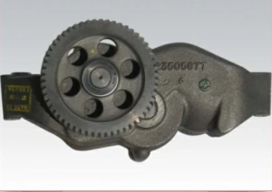
The gear-driven oil pump ensures consistent oil flow and pressure throughout the engine, which is critical for maintaining lubrication and cooling under both normal and high-load conditions. Located at the front of the engine and driven directly by the crankshaft, the pump uses internal helical gears to draw oil from the pan and pressurize it before distributing it through the engine’s lubrication galleries. The helical gear design helps to reduce noise and allows for smoother operation compared to straight-cut gears.
Removal and Installation
- Drain the oil completely from the oil pan to avoid spills.
- Loosen and remove all bolts securing the oil pump to the front cover or housing.
- Carefully detach the inlet and outlet pipes, taking note of their orientation and condition.
- Inspect the sealing surfaces for any damage or debris.
- During reinstallation, reverse the process and use new gaskets or O-rings as required.
- Ensure all mounting bolts and pipe fittings are torqued to manufacturer specifications.
- Once installed, refill the engine with oil and prime the lubrication system before starting.
Inspection and Repair
A thorough inspection of the oil pump during service can help avoid engine damage caused by low oil pressure. Key inspection points include:
- Check pump bushings for scoring or ovality.
- Measure gear tooth wear and backlash.
- Examine the pump housing for cracks or pitting.
- Check that the gear teeth rotate freely without binding.
- Verify pump clearances and replace any components that exceed allowable tolerances.
If wear is detected beyond service limits, replace the affected parts or the entire pump. After assembly, rotate the pump manually to ensure smooth, resistance-free movement.
Specifications and Tolerances
- Drive Gear Clearance: 0.051–0.229 mm (0.002–0.009 in.)
- Endplay (Axial Play): 0.084–0.112 mm (0.0033–0.0044 in.)
- Maximum Acceptable Wear: Replace parts if clearances exceed 0.089 mm (0.0035 in.) in bushing or gear-to-gear clearance.
Maintaining proper tolerances and following recommended inspection procedures is essential to keep the Series 60 engine’s oil delivery system functioning efficiently and to prevent costly engine damage caused by lubrication failure.
Oil Pressure Regulation
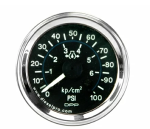
Pressure Regulator Valve Operation
The oil pressure regulator valve plays a central role in stabilizing system pressure. As engine speed and temperature fluctuate, this valve ensures that oil pressure remains within a safe operating window. The valve is spring-loaded and begins to open at approximately 310 kPa (45 psi), allowing excess oil to return to the sump. This regulation protects bearings and other components from excessive force, particularly at high RPM or cold-start conditions when oil is thicker and flows less freely.
Relief Valve Details
The pressure relief valve provides a secondary layer of protection. It is calibrated to open at 724 kPa (105 psi), which prevents potentially damaging pressure spikes that could rupture oil filters or seals. This valve is especially important during cold starts or periods of rapid acceleration, where oil viscosity and flow rates change rapidly. It serves as a critical safeguard in the event the regulator valve fails to react quickly enough.
Repair and Replacement
Routine inspection and maintenance of the pressure regulation system are essential for sustained engine health. If signs of pitting, rust, deformation, or spring fatigue are observed, both the regulator and relief valves should be replaced. Always clean components with fuel oil or a suitable solvent, then inspect the valve seat, spring tension, and housing bore for any signs of wear or obstruction. Binding or delayed valve operation can lead to insufficient lubrication or pressure surges, risking serious engine damage. Replacing these small but vital components on schedule helps ensure consistent oil delivery and overall engine reliability.
Oil Filters
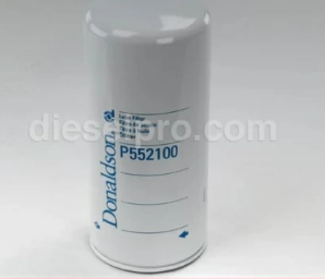
Types of Oil Filters
-
Full-Flow Filters: These are the primary filters in most engine lubrication systems. They remove contaminants such as metal particles, soot, and carbon from all the oil flowing through the engine, ensuring that every moving component receives clean, pressurized lubrication.
-
Bypass Filters: Used in conjunction with full-flow filters, bypass filters process a small portion of the oil at a time and are designed to trap finer particles—down to sub-micron levels. They enhance overall cleanliness and are especially useful in extended service interval or high-contamination environments.
-
Spin-On vs. Cartridge Filters: Spin-on filters combine the housing and filter element in one unit for easy replacement, while cartridge filters use a replaceable element inside a permanent housing, reducing waste and often found in newer engine designs.
Replacement Intervals and Techniques
-
Replace oil filters approximately every 24,000 kilometers (15,000 miles) for trucks or during each oil change, depending on the application and oil quality. Engines operating in severe duty (e.g., marine, dusty, or high-load environments) may require shorter intervals.
-
Always coat the rubber seals on new filters with clean engine oil before installation to ensure proper seating and prevent leaks.
-
Tighten filters by hand until the seal contacts the mounting surface, then give an additional ¾ to 1 full turn as specified by the manufacturer. Avoid over-tightening, which can damage the gasket or filter housing.
-
Inspect old filters for metal shavings or abnormal residue, which could indicate internal wear or contamination issues elsewhere in the engine.
Oil Cooler
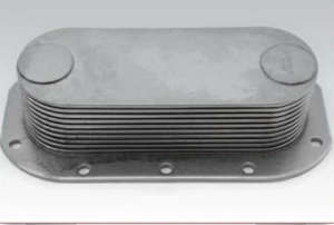
Function and Design Variations
The oil cooler plays a critical role in maintaining engine longevity by regulating oil temperature and preventing thermal breakdown. By dissipating heat absorbed from internal engine components, the cooler helps keep lubricating oil within its optimal operating range—typically between 180°F and 200°F (82°C to 93°C). This ensures that the oil maintains proper viscosity for efficient lubrication and cooling. Overheating can lead to oil degradation, increased wear, and premature failure of engine parts.
Modern oil cooler designs, especially those produced after 1991, often feature an integrated bypass mechanism. This safety feature allows oil to bypass the cooler core if it becomes clogged or restricted, preventing oil starvation and maintaining flow to critical engine parts. These enhancements improve reliability in high-contamination or extreme-temperature environments and are particularly valuable in marine and industrial applications where access to service may be limited.
Cleaning and Inspection
Regular inspection and cleaning of the oil cooler is essential for optimal performance. Over time, sludge, debris, or mineral buildup can reduce heat transfer efficiency. Clean the core using alkaline cleaning solutions or Tech Solv 340, a solvent specifically formulated for dissolving oil and particulate residue. Ensure thorough flushing of both the oil and coolant sides to eliminate cross-contamination.
To check for leaks or compromised integrity, perform a pressurized air test between 75–100 psi while submerging the unit in water. Bubbles indicate a leak and warrant repair or replacement. Be sure to also inspect the core and housing for corrosion, cracks, or distorted fins that may impact cooling efficiency.
Installation Procedures
When reinstalling the oil cooler, it’s important to replace all O-rings, seals, and gaskets with new ones to prevent leaks and ensure a secure fit. Before torqueing any bolts, confirm that all mating surfaces are clean and free of debris. Tighten bolts in the correct cross-pattern sequence to a torque specification of 30–38 Nm (22–28 ft-lb). Uneven torqueing can warp the housing or lead to coolant and oil leaks.
For comprehensive maintenance, always verify your work against factory service manuals, including torque specs and flow direction. Using high-quality aftermarket components—such as those available from Diesel Pro Power—can enhance reliability and performance, particularly in commercial, marine, and off-highway applications where durability is mission-critical.
Parts Catalog for 11.1L Detroit Diesel 60 Series Marine Engine
Parts Catalog for 12.7L Detroit Diesel 60 Series Marine Engine
Parts Catalog for 14L Detroit Diesel 60 Series Marine Engine
Additional Resources For The Detroit Diesel Series 60
General Information Part 1 For Detroit Diesel Series 60 Engines (11.1L, 12.7L, 14L)
Engine Systems and Components For Detroit Diesel Series 60 Engines (11.1L, 12.7L, 14L)
Fuel System For Detroit Diesel Series 60 Engines (11.1L, 12.7L, 14L)
Engine Components and Overhauls For Detroit Diesel Series 60 Engines (11.1L, 12.7L, 14L)
Systems Maintenance For Detroit Diesel Series 60 Engines (11.1L, 12.7L, 14L)
Electronic Systems For Detroit Diesel Series 60 Engines (11.1L, 12.7L, 14L)
Maintenance Schedules and Best Practices For Detroit Diesel Series 60 Engines (11.1L, 12.7L, 14L)
Appendices for Detroit Diesel Series 60 Engines (11.1L, 12.7L, 14L)
Lubrication System For Detroit Diesel Series 60 Engines (11.1L, 12.7L, 14L)
Cooling System for Detroit Diesel Series 60 Engines (11.1L, 12.7L, 14L)
Fuel System for Detroit Diesel Series 60 Engines (11.1L, 12.7L, 14L)
Electrical Equipment and Sensors for Detroit Diesel Series 60 Engines (11.1L, 12.7L, 14L)
Preventive Maintenance for Detroit Diesel Series 60 Engines (11.1L, 12.7L, 14L)
Appendices for Detroit Diesel Series 60 Engines (11.1L, 12.7L, 14L)
Step-by-Step Overhaul Procedure for Detroit Diesel Series 60 Engine (11.1L, 12.7L, 14L)
Differences Between 3 Detroit Diesel Series 60 Engines (11.1L, 12.7L, and 14.7)