

 Free US Calls: 1-888-433-4735
 International: 305-545-5588
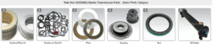
Parts catalog for Twin Disc MG50590A Marine Transmissions
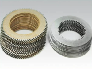
Overhaul Plate Kit For Twin Disc MG5090A Marine Transmission
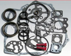
Gasket Kits For Twin Disc MG5090A Marine Transmission
Introduction: The Importance of Proper Reassembly for MG-5090A Reliability
Reassembling the Twin Disc MG-5090A marine gear after a teardown, cleaning, or rebuild is a precision operation. Every component—from clutch discs and reduction gears to oil seals and bolts—must be returned to its exact position, with the right amount of torque, lubrication, and alignment.
Reassembly is not just about putting everything back together. It’s about restoring the transmission to like-new performance, ensuring:
- Correct hydraulic pressure
- Precise gear alignment
- Proper shaft tolerances
- Leak-free sealing
- Smooth and silent clutch engagement
This comprehensive reassembly guide will help mechanics, boat owners, and marine technicians complete the MG-5090A reassembly process accurately and confidently, with practical, real-world instructions for each step.
Preparation Before Starting Reassembly
Before a single bolt is turned, make sure the work environment and components are ready for precision reassembly.
Clean Workspace
- Use a lint-free, metal-free bench top for component layout
- Segregate cleaned parts from old, worn, or contaminated items
- Lay out parts in order of installation
Verify Replacement Parts
Ensure you have:
- Correct gasket and seal kit
- Rebuild kit for clutch, bearings, and gears (if applicable)
- Proper torque specifications (from OEM manual)
- Replacement bolts, snap rings, shims, and washers if damaged
- Premium marine-grade transmission oil
Tip: Diesel Pro Power offers complete rebuild kits with seals, friction plates, bearings, gaskets, and installation guides for the MG-5090A.
Gather Required Tools
- Torque wrenches (in-lbs and ft-lbs)
- Assembly lube
- Bearing driver set or press
- Snap ring pliers
- Feeler gauges
- Dial indicator with magnetic base
- Loctite (medium strength) and anti-seize compound
- Rubber mallet and dead-blow hammer
- Thread chaser or tap/die kit (optional)
Step-by-Step Reassembly Procedure
Step 1: Lubricate Bearings and Shafts
Before inserting any rotating components:
- Apply a light coat of assembly lube (zinc or moly-based) to:
- Inner and outer bearing races
- Shaft journals and gear bores
- Thrust washer and bearing faces
Why assembly lube?
- Prevents dry-start damage
- Ensures proper preload on bearings
- Provides corrosion protection during first startup
Note: Do not use general-purpose grease or wheel bearing grease—it may interfere with hydraulic clutch actuation or oil circulation.
Step 2: Install Bearings and Seals
Using a seal installer or soft mallet:
- Seat all shaft seals evenly—do not tilt or overdrive
- Confirm proper depth using the OEM measurement
- Apply a film of oil on seal lips before shaft insertion
Install bearings:
- Heat bearing (if required) to 250°F using a bearing heater
- Use press or driver set for cold fit bearings
- Never hammer bearings onto shafts directly
Critical Tip: Misaligned or skewed bearings will damage shafts or retainers and must be reinstalled.
Step 3: Assemble Gears and Shafts
Reinstall gears in their marked orientation:
- Begin with the input shaft assembly
- Follow with sun gear, planetary carrier, and ring gear
- Position thrust washers and spacers as marked during teardown
- Insert output shaft assembly
Step 4: Reinstall Clutch Packs
Install clutch plates and friction discs:
- Alternate steel and friction discs
- Soak friction plates in clean transmission oil for 30 minutes
- Stack to proper height as specified in the OEM manual
- Ensure tabs and splines align with drum and hub
Install piston and spring assembly:
- Use correct orientation
- Lightly oil all O-rings and seals
- Compress evenly and secure with snap rings or retaining bolts
Check end clearance with feeler gauges before finalizing clutch assembly.
Step 5: Replace All Gaskets and Sealing Surfaces
Install new gaskets on:
- Inspection covers
- Input/output shaft housings
- Valve body or control cover
- Side inspection ports
Apply non-hardening gasket compound if recommended by the OEM. Do not reuse gaskets—they will not reseal properly after compression.
Sealing Tips:
- Avoid over-applying RTV sealant; it may enter oil passages
- Use thread sealant on bolts that enter oil or water jackets
- Confirm gasket alignment before torqueing bolts
Step 6: Torque All Bolts to OEM Specifications
Each bolt must be torqued correctly for load integrity, sealing, and safety.
Recommended Torque Procedure:
- Use a calibrated torque wrench
- Clean bolt threads and mating holes
- Apply Loctite 242 (blue) on high-vibration fasteners
- Tighten bolts in a crisscross sequence for covers and housings
- Record torque values for future inspection
Typical Torque Ranges (Always consult your manual):
| Bolt Location | Torque Spec (Example) |
| Input shaft housing | 35–45 ft-lbs |
| Inspection cover bolts | 20–25 ft-lbs |
| Valve body bolts | 15–18 in-lbs |
| Output shaft flange | 60–75 ft-lbs |
Post-Reassembly Testing and Verification
Step 1: Fill With Approved Oil
- Use SAE 30 transmission oil (per Twin Disc specification)
- Fill through the designated fill cap on the transmission
- Allow oil to settle for 10–15 minutes, then recheck level
- Do not overfill—this can cause foaming and loss of pressure
Step 2: Manual Gear Test (Pre-Start)
- Rotate input shaft manually
- Engage forward and reverse manually at the lever
- Listen and feel for smooth transitions and proper detent clicks
- Watch for binding, scraping, or improper gear contact
Step 3: Start Engine and Run in Neutral
- Monitor oil pressure gauge (250–300 PSI engagement pressure)
- Let engine idle for 5–10 minutes
- Check for oil leaks, seal weeping, or pressure fluctuations
- Shift to forward and reverse briefly—each gear should engage smoothly
- Return to neutral and shut down
Step 4: Recheck Bolt Torque and Oil Level
- After cool-down, check torque on major housing and cover bolts
- Confirm oil is at correct level on dipstick (engine idling in neutral)
- Inspect filter for any metal or residue
Step 5: Run Under Load (Dock Test)
- Secure vessel to dock with lines
- Shift into gear under load and throttle slightly
- Monitor:
- Engagement time (should be <1 sec)
- Noise or vibration
- Gear backlash
- Overheating
Let transmission operate under load for 30–45 minutes.
Step 6: Recheck Clutch Pressure and Performance
After one hour of operation:
- Measure clutch engagement pressure at test ports
- Recheck for any loss of pressure, oil foaming, or inconsistent engagement
- Recheck oil for discoloration or metallic sheen
Troubleshooting Reassembly Mistakes
Slipping or Delayed Engagement
- Incorrect clutch stack height
- Internal seal failure
- Misadjusted control lever or actuator
- Low oil pressure from incorrect oil or faulty pump
Whining or Vibration
- Misaligned gears or shaft
- Improper bearing preload
- Loose housing bolts
- Excess backlash
Oil Leaks
- Damaged or misaligned gasket
- Improperly seated seal
- Overfilled transmission
- Loose drain plug or fill cap
No Engagement
- Incorrect piston seal installation
- Clutch plates installed backward
- Blocked hydraulic passage
- Air trapped in system
Pro Tips for Success
- Photograph each step during disassembly for reference
- Label parts and bag small hardware to avoid confusion
- Use OEM torque specs—guessing leads to failure
- Inspect all components before reuse—especially shims and thrust washers
- Document reassembly in a service log with dates, torque specs, and parts used
- Replace any fastener that shows signs of stretch, rust, or thread wear
When to Rebuild vs. Replace
Reassembly is the final step of a successful rebuild. However, if your transmission:
- Shows multiple gear or bearing failures
- Has cracked housings or mounting ears
- Has had repeated clutch failures
- Is cost-prohibitive to repair internally
…it may be time to consider a remanufactured MG-5090A.
Diesel Pro Power Offers:
- Fully rebuilt and tested MG-5090A transmissions
- Rebuild kits with gaskets, seals, bearings, and clutch discs
- Torque spec guides and reassembly resources
- Global shipping and expert customer support
Summary: Precision Reassembly Equals Peak Performance
The Twin Disc M
G-5090A is a robust, high-performance marine gear—but only when rebuilt and reassembled to exacting standards. Following a disciplined reassembly process with the right tools, torque specs, and lubrication ensures:
- Leak-free operation
- Smooth gear engagement
- Optimal clutch pressure
- Long service life
Whether you’re restoring a commercial transmission or overhauling your fishing vessel’s drivetrain, this guide gives you the confidence to complete the job correctly—or know when to call in the experts.
Reassembly Quick Reference Table
Step |
Key Action |
Tools Required |
| Bearing Installation | Lube and press or heat-fit | Bearing heater, driver set |
| Shaft and Gear Assembly | Align marked components, install thrust washers | Torque wrench, mallet |
| Clutch Stack Assembly | Soak plates, install with correct stack height | Feeler gauge, caliper |
| Gasket and Seal Replacement | Use new parts, align carefully | Gasket scraper, seal driver |
| Final Torque | Follow OEM spec, tighten crisscross | Torque wrench (in-lb/ft-lb) |
| Initial Startup | Monitor pressure, temperature, shifting | Pressure gauge, IR thermometer |
| Post-Run Check | Inspect bolts, oil, pressure | Dipstick, wrench, gauge |
Overhaul Plate Kit For Twin Disc MG5090A Marine Transmission
Gasket Kits For Twin Disc MG5090A Marine Transmission
Videos About Twin Disc Transmissions
6 Reasons Your Twin Disc Transmission Has Low Oil Pressure
7 Reasons Your Twin Disc Transmission Is Overheating
3 Reasons Your Clutch Plates in Your Twin Disc Transmission Are Making Excessive Noise
Bull Gear On A Twin Disc Transmission
Rebuilt Twin Disc Transmissions