

 Free US Calls: 1-888-433-4735
 International: 305-545-5588

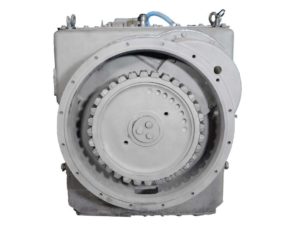
The Twin Disc MG-540 marine gear is a heavy-duty transmission requiring precise mechanical procedures during both removal and reinstallation. Mistakes during these processes can lead to misalignment, leaks, damage to mating surfaces, or premature component failure. This section expands upon the complete step-by-step approach for removing, transporting, reinstalling, and aligning the MG-540, ensuring reliable operation and full compliance with best installation practices.
Removing Transmission From Engine and Driveline
Step 1: Secure the Work Area
- Ensure the vessel is docked securely and power is shut off.
- Follow lockout/tagout procedures: disconnect batteries and ignition keys.
- Drain transmission oil completely to prevent spills.
Step 2: Disconnect External Systems
- Label and remove control linkages (mechanical or electric).
- Disconnect hydraulic lines, cooling lines, and any solenoid connectors.
- If equipped with EC050 or electric control, protect exposed terminals with caps.
Step 3: Support the Transmission
- Use lifting lugs on the MG-540 housing. These are designed to support the weight of the transmission only, not the entire engine-transmission assembly.
- Use a chain hoist or engine crane with spreader bar to prevent housing stress.
Step 4: Unbolt From Engine Flywheel Housing
- Remove the bolts evenly, working in a crisscross pattern.
- Secure the transmission using guide studs or dowel pins to prevent unexpected movement.
- Separate from the flywheel housing using jack screws or a mechanical wedge if necessary.
Step 5: Disconnect Propeller Coupling
- Loosen and remove the bolts from the output flange coupling.
- Mark alignment points for reinstallation (coupler to shaft and flange to hub).
- Carefully slide the coupling off the shaft.
Protecting Mating Surfaces During Transport
Surface Protection Protocol
- Clean all mating surfaces using solvent and a lint-free rag.
- Apply a light coat of transmission oil to flanges, shafts, and coupler bores to prevent corrosion.
Recommended Materials
- Plastic or soft rubber flange protectors
- Non-abrasive foam pads between machined faces
- Plastic wrap secured with tie wire or protective shipping tape
During Transport
- Place the MG-540 in a horizontal position on a cradle or pallet with vibration-dampening material.
- Do not rest the gear on the output flange or input shaft.
- Strap securely and avoid contact with hard surfaces.
Reinstallation Torque Sequences and Seal Prep
Pre-Torque Preparations
- Clean all fasteners and threaded holes.
- Lubricate threads with a light oil film (not grease).
- Install new gaskets, seals, and O-rings. Never reuse old gaskets.
Seal Preparation and Installation
- Use Loctite 17430 (M2828) sealant for front housing faces, bottom pan, and dowel pin holes.
- Install seals using Twin Disc tools:
- T-21552-188 for SAE 0
- T-21552-191 for SAE 00
Seal Depth Tip: Install until flush with seal housing using the seal driver tool. Apply oil film on seal lips prior to shaft insertion.
Torque Specifications Overview
| Fastener | Size | Torque |
| Flywheel housing to gear | 1/2-13 | 65 lb-ft |
| Output coupling bolts | 3/4-10 | 245 lb-ft |
| Bottom cover bolts | 1/2-13 | 65 lb-ft |
| Seal carrier to housing | 1/2-13 | 65 lb-ft |
| Mounting brackets to bed | 5/8-11 | 140 lb-ft1 |
Final Alignment and Coupler Mating
Correct final alignment ensures optimal bearing and gear life. It must be performed only when the boat is in water and fully loaded to normal trim.
Step 1: Align Transmission to Propeller Shaft
- Use a 0.05 mm (0.002 in) feeler gauge around the entire output flange.
- Rotate the flange in 90° increments and check for consistent resistance.
- If alignment varies, rework engine or shaft position.
Maximum Output Flange Runout: 0.10 mm (0.004 in)
Adjust by rotating flange on taper or reworking shaft key.
Step 2: Align Engine to Transmission
- Use jacking screws at each engine mount corner.
- Shim steel plates under mounting pads for vertical adjustment.
- Use a jack to shift engine laterally for horizontal alignment.
- Check parallelism with a straight edge across coupling faces.
Zero-Deflection Tip: Use a dial indicator on the transmission to monitor housing deflection as bolts are tightened. The indicator must stay at 0.
Step 3: Final Coupler Mating
- Align scribed marks on coupler and flange from disassembly.
- Use anti-seize compound on taper surfaces, but keep mating faces dry.
- Torque bolts in a crisscross pattern.
Verify Coupler Fit:
- No gaps or rocking movement.
- Test shaft rotation by hand with no binding.
- Check for fretting or mismatch after tightening.
Post-Reinstallation Checks
| Task | Description |
| Oil Level | Refill and confirm with engine off, gear in neutral |
| Seals | Visually confirm no pinched or damaged gaskets |
| Solenoids and Valves | Connect wiring harnesses, confirm ground |
| Pressure Test | Run pressure checks in FWD, NEUTRAL, REV |
| Final Leak Check | Inspect housing, coupler, and manifold for oil leakage |
Pro Tip: Run engine at idle and observe oil temperature. Let gear reach 140°F, then torque output coupling bolts again after thermal cycling.
Summary
Removing and reinstalling the Twin Disc MG-540 marine transmission is a methodical process involving mechanical precision, cleanliness, and careful alignment. This procedure includes:
- Proper lifting and decoupling
- Surface preservation during transport
- Full torque specification charts
- Seal installation using OEM-approved techniques
- Coupling alignment per SAE J-1033 and J-617
By following this guide, technicians can guarantee a secure fit, optimal alignment, and full operational readiness of the MG-540 gear.
Videos About Twin Disc Transmissions
6 Reasons Your Twin Disc Transmission Has Low Oil Pressure
7 Reasons Your Twin Disc Transmission Is Overheating
3 Reasons Your Clutch Plates in Your Twin Disc Transmission Are Making Excessive Noise
Bull Gear On A Twin Disc Transmission
Rebuilt Twin Disc Transmissions