

 Free US Calls: 1-888-433-4735
 International: 305-545-5588

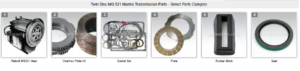
Parts Catalog for Twin Disc MG521 Marine Transmissions
Rebuilt Twin Disc MG521 Marine Transmissions
Plate Kit For Twin Disc MG521 Marine Transmission
Gasket Kits For Twin Disc MG521 Marine Transmission
Removing and reinstalling the Twin Disc MG521 marine transmission is a significant undertaking that requires precision, planning, and adherence to safety protocols. Whether you’re pulling the gearbox for service, replacing worn internal components, or installing a remanufactured unit, following the correct procedure ensures you avoid equipment damage, misalignment, or premature wear after reinstallation.
This comprehensive guide details every critical step from removal through post-installation testing.
Disconnecting From Engine and Shaft
1. Prepare the Work Area
Before any mechanical work begins:
- Ensure the engine is off and has cooled completely.
- Disconnect battery power to avoid accidental starter engagement.
- Make sure the vessel is docked securely or on a dry dock.
- Assemble all necessary tools including wrenches, ratchets, pry bars, drip pans, and lifting equipment.
2. Drain Hydraulic and Control Lines
- Label all hydraulic and electronic connections.
- Use a catch pan to collect hydraulic fluid.
- Cap open fittings to prevent contamination or drips.
- Disconnect EC300 connectors or shift cables at the transmission.
3. Detach the Propeller Shaft Flange
- Mark the shaft and flange orientation with a paint pen to maintain original alignment.
- Use a dial indicator to measure shaft runout for reference.
- Unbolt the coupling flange (usually 4 to 6 bolts).
- Carefully slide the shaft back or suspend it to avoid contact with the transmission housing.
Important: If the shaft cannot be moved aft far enough, you may need to unbolt the shaft strut or remove the propeller to create clearance.
4. Disconnect From the Engine Bell Housing
- Support the rear of the engine with a jack or hoist if the transmission is also functioning as a mount.
- Remove all bell housing bolts in a star pattern to avoid binding.
- If mounted with dowel pins, use flat pry bars to gently break the seal.
- Ensure input shaft does not bind as you pull the transmission away from the engine flywheel or coupling.
Draining Oil and Safe Containment
1. Tools and Materials Needed
- Oil suction pump or socket for drain plug
- Oil catch pan (at least 5-gallon capacity)
- Spill pads and gloves
- Sealed waste oil container for disposal
2. Draining Process
- Remove the transmission oil filler cap to allow air in.
- Place the catch pan under the drain plug or suction port.
- Open the drain plug slowly to allow oil to flow without splashing.
- Drain until no more fluid exits.
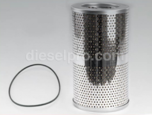
- Remove and dispose of the oil filter.
3. Safe Oil Disposal
- Collect used oil in an approved container.
- Label the container with date and source.
- Dispose of waste oil through a certified marine waste contractor or recycling center.
4. Cleaning Up
- Wipe the gearbox housing with clean rags.
- Remove any oil that may have spilled on mounts or engine bed.
- Inspect for signs of metal debris or contamination in the oil.
Lifting Techniques and Rigging Requirements
The MG521 marine gear weighs between 400–550 lbs depending on configuration. Lifting improperly can cause equipment damage or serious personal injury.
1. Rigging Tools Required
- Chain hoist or hydraulic crane (rated minimum 1,000 lbs)
- Lifting straps or chains
- Lifting eye bolts for gear housing (use OEM lifting points only)
- Spreaders or slings to balance the load
- Protective gear (hard hat, gloves, steel toe boots)
2. Rigging Procedure
- Use the threaded lifting holes on the top of the gear housing.
- Insert rated lifting eyes and torque them securely.
- Attach straps or chains and connect to the hoist using a spreader bar if needed to avoid side loading.
- Lift the unit slowly, keeping it level.
- Avoid standing underneath the suspended load.
- Guide the gearbox manually into its removal path.
Tip: Use tag lines for control if clearance is tight.
3. Storage
- Place the removed MG521 on a flat, padded surface or transmission dolly.
- Cap all open ports and wrap the gear in a breathable cover.
- Do not store outdoors or in areas exposed to salt spray.
Inspection Before Reinstallation
Before reinstalling the MG521 or installing a new/rebuilt unit, thorough inspection is critical to prevent future issues.
1. Inspect the Engine Bell Housing
- Check for cracks, burrs, or worn mounting surfaces.
- Clean any oil or residue from alignment dowels.
- Inspect flywheel or coupling plate for wear or broken teeth.
2. Examine the Mounting Base
- Ensure mounting pads are level and free of rust or deformation.
- Replace any soft or collapsed engine mounts.
- Shim the base to correct for any soft foot conditions.
3. Review Shaft and Coupling Condition
- Clean the output flange on the MG521 and the mating propeller shaft flange.
- Check for concentric alignment and radial runout.
- Replace flexible coupling if rubber elements are cracked or flattened.
- Lubricate shaft splines or keyways with anti-seize compound.
4. Inspect Hardware and Fasteners
- Discard and replace any worn or stretched bolts.
- Clean threads and apply anti-corrosion compound.
- Confirm all bolt threads match housing and flange thread pitch.
5. Pre-Install Clutch Function Test
- Manually rotate the input shaft.
- Engage shift lever and observe smooth movement into forward and reverse.
- Check for binding or excessive play.
Re-Torquing Mounting and Coupling Hardware
Correct torque is essential for mechanical integrity. Overtightening can crack the housing, while undertightening leads to shifting and vibration.
1. Mounting Bolt Torque Specs
Bolt Size |
Torque (lb-ft) |
| 3/8”-16 | 33–37 |
| 1/2”-13 | 75–85 |
| 5/8”-11 | 150–165 |
| 3/4”-10 | 250–275 |
- Use hardened flat washers under bolt heads.
- Apply Loctite 271 or equivalent threadlocker.
- Re-torque bolts after 25 hours of operation.
2. Flange Coupling Torque Specs
- Align index marks made during disassembly.
- Torque in a star pattern to ensure even clamping.
- Use anti-seize on flange bolts to prevent galling.
3. Control Linkage Torque
- For mechanical systems, torque clevis bolts to 12–15 lb-ft.
- Adjust cable tension for neutral detent and full travel.
- Secure control cables with cushioned clamps every 18 inches.
Oil Refill and Priming Procedure
After the gear is reinstalled and all connections are secured, it must be filled with clean oil and primed before starting.
1. Oil Type and Capacity
- Recommended Oil: SAE 30 non-detergent or approved marine transmission fluid.
- Capacity: Approx. 2.5–3.5 gallons depending on model and oil cooler volume.
2. Filling Procedure
- Remove the filler plug or cap.
- Fill oil slowly to the “Full” mark on the sight glass or dipstick.
- Allow 10 minutes for oil to settle before rechecking.
- Top off if level drops.
3. Priming the System
Manual Priming:
- Turn the input shaft by hand to move oil through galleries.
- If available, use a hand pump to fill oil passages.
Crank-Priming (Alternate Method):
- Disable fuel or ignition.
- Crank engine in 10-second bursts.
- Monitor oil pressure gauge for movement.
- Reconnect fuel and start when pressure builds.
Key Checkpoints:
- Look for oil circulation in cooler lines.
- Observe sight glass for aeration or foam.
- Recheck level after engine idles for 5 minutes.
Operational Checks After Reinstallation
With installation and priming complete, the MG521 is ready for functional testing. These checks ensure all systems operate correctly before putting the vessel under load.
1. First Start-Up
- Start engine and keep throttle at idle.
- Confirm oil pressure reaches 200–250 PSI within 5 seconds.
- Watch for leaks at fittings, flanges, and drain plug.
2. Shift Engagement
- Shift from NEUTRAL to FORWARD and REVERSE.
- Confirm smooth engagement without clunking or delay.
- Listen for whining, clicking, or hesitation.
3. Visual Inspection
- Use a flashlight to check all fittings and seals.
- Confirm control linkage or actuators respond properly.
- Look for oil drips or seepage from new seals.
4. Vibration and Alignment Check
- Observe gearbox and mounts while engine is running.
- Vibration should be minimal and consistent.
- Recheck flange alignment if excessive movement occurs.
5. Final Checks Under Load
- Perform dockside test at idle and low RPM.
- Slowly increase throttle while shifting into gear.
- Check for:
- Smooth clutch response
- Oil pressure stability
- No slipping or vibration
6. Documentation and Logging
- Record the date, oil type, filter used, and torque settings.
- Log operating hours at reinstallation.
- Set reminders for 25-hour post-installation inspection.
Conclusion: Seamless Removal and Reinstallation for MG521 Reliability
A successful Twin Disc MG521 marine gear removal and reinstallation project depends on attention to detail, accurate alignment, and strict adherence to torque and priming procedures. Whether you’re replacing a damaged gear or servicing a worn unit, the goal is always the same: maximum uptime, performance, and safety.
Diesel Pro Power provides everything you need for this job:
- Complete MG521 rebuild kits
- Oil filters and seals
- Bell housing bolts and flange hardware
- Mounting pads and shims
- Hydraulic servos and EC300 electronic controls
- Premium transmission oil
Rebuilt Twin Disc MG521 Marine Transmissions
Plate Kit For Twin Disc MG521 Marine Transmission
Gasket Kits For Twin Disc MG521 Marine Transmission
Videos About Twin Disc Transmissions
6 Reasons Your Twin Disc Transmission Has Low Oil Pressure
7 Reasons Your Twin Disc Transmission Is Overheating
3 Reasons Your Clutch Plates in Your Twin Disc Transmission Are Making Excessive Noise
Bull Gear On A Twin Disc Transmission
Rebuilt Twin Disc Transmissions