

 Free US Calls: 1-888-433-4735
 International: 305-545-5588
The Twin Disc MG5114A marine transmission is built for longevity, but like any heavy-duty marine component, there will come a time when it must be removed—whether for a clutch pack replacement, full overhaul, input seal change, or complete unit swap.
Because of its integration with the engine, drivetrain, and hydraulic systems, removing and reinstalling the MG5114A is a task that requires careful planning, proper lifting tools, and alignment. When done incorrectly, you risk damaging the transmission, engine mounts, and shafts or even injuring personnel.
This section walks you through step-by-step procedures for safely removing and reinstalling the MG5114A transmission on a marine vessel, using best practices from seasoned marine mechanics and industry technicians.
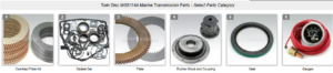
Parts Catalog for Twin Disc MG5114A Marine Transmissions
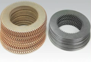
Plate Kit For Twin Disc MG5114A Marine Transmission
Gasket Kits For Twin Disc MG5114A Marine Transmission
Removal Procedure for Twin Disc MG5114A Marine Gear
Before removing the MG5114A from the vessel, ensure that the engine is shut down, battery banks are disconnected, and you’ve informed all crew members that service is underway.
Step 1: Disconnecting Control Cables and Hydraulic Lines
The first step is to isolate the transmission from all auxiliary systems.
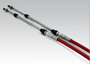
Control Cables
- If the gear is mechanically controlled, locate the shift linkage arm on the control valve and:
- Remove the cotter pin or retaining clip
- Unscrew the ball joint or rod end
- Label the linkage position for reassembly
- For electronic controls, disconnect:
- Electrical plugs for solenoids
- CAN bus or wiring harness connectors
- Mounting clips or cable supports
Always label wires and connectors with masking tape or zip tags. This ensures no confusion during reinstallation.
Hydraulic Lines
- Place oil-absorbent pads and spill trays beneath all fittings
- Use line wrenches to avoid rounding off soft brass or aluminum fittings
- Cap or plug the ports immediately after disconnecting to prevent contamination
- Label each line (forward clutch, reverse clutch, cooler return, etc.)
Cooling Lines
- Disconnect inlet and outlet hoses from the transmission oil cooler
- Plug lines and ports to prevent air entry or spillage
- Inspect hoses for wear, cracks, or internal collapse—replace if suspect
Pro Tip: Use color-coded zip ties or tags to track hose positions. Many leak issues come from misrouted or reversed lines during reinstallation.
Step 2: Draining the Transmission
Before unbolting or moving the transmission, drain all oil from the housing.
- Use the drain plug or suction pump to remove fluid
- Collect oil in a marked container for disposal or oil analysis
- Remove the dipstick or vent to allow airflow and speed up drainage
- Once drained, reinstall the drain plug with sealant or a new washer
Never attempt to move the MG5114A with oil inside—it increases weight and risks spillage in the bilge.
Step 3: Supporting Transmission Weight Safely
At this stage, the transmission is still bolted to the engine and mounts—but it’s time to prepare for removal.
Transmission Weight
The MG5114A typically weighs between 850–950 lbs depending on oil cooler configuration and reduction ratio. Do not attempt to move it manually.
Lifting Tools
- Use a marine-grade chain hoist, engine crane, or gantry beam
- Attach to designated lifting eyes or brackets on the gear housing
- Never lift by cooler ports, oil lines, or shift arms
- Use a load spreader or lifting sling to balance the unit evenly
Place timber blocks or padded stands beneath the gear to support it in case of hoist failure.
Warning: If the gear shifts unexpectedly or drops during removal, it can damage the propeller shaft, engine flywheel, or mounting brackets.
Step 4: Removing Bolts from Bellhousing and Mounts
With the weight secured and supported:
Bellhousing Bolts
- Locate and remove the bolts that mate the gear housing to the engine flywheel housing
- These are typically 12–16 mm bolts, torqued tightly and sealed with threadlocker
- Use breaker bars or impact tools if necessary—but always support the gear during this stage
Tip: Mark bolt positions and store hardware in labeled bags or containers to avoid mismatching threads.
Output Shaft Coupling
- Remove the bolts from the companion flange or flexible coupling
- Carefully separate the output shaft from the propeller shaft
- Slide the shaft aft or brace it securely if the propeller is still in place
Mounting Feet
- Remove bolts from the gear’s mounting feet to the stringers or bedplate
- Inspect the rubber isolation mounts—replace if cracked, oil-soaked, or separating
Once unbolted, carefully slide the gear aft and lift it free of the engine. Lower it onto a pallet, stand, or skid platform for transport to the workshop or dock.
Installation Procedure for Twin Disc MG5114A Marine Gear
Reinstalling the MG5114A is essentially the reverse of removal—but with extra care taken to ensure perfect alignment, correct torque values, and proper sealing.
Always inspect the transmission for wear or damage before reinstalling. Common reinstallation includes new:
- Input and output seals
- Mount bushings
- Oil and filter
Step 1: Flywheel Housing Alignment
Proper alignment between the engine flywheel and transmission input shaft is critical. Misalignment causes:
- Premature wear of the input bearing
- Excessive gear noise
- Shaft spline wear
- Mount fatigue and cracking
Procedure:
- Inspect flywheel housing for cracks or corrosion.
- Verify that the damper plate is:
- The correct thickness
- Installed with clean hardware
- Free of warping or worn springs
- Use alignment dowels or guide studs when bringing the transmission forward
- Rotate the engine slightly by hand if the input shaft splines do not engage smoothly
- Never force the gear into place with bolts—this indicates misalignment
Check for face runout and shaft misalignment with feeler gauges or dial indicators. Tolerances should be within 0.003 inches TIR.
Step 2: Bolt Torque and Sequence (General Reference)
Once aligned, begin securing the gear with clean bolts and proper lubrication or thread sealant.
Bellhousing Bolts
- Hand-thread all bolts before applying torque
- Tighten in a star pattern, alternating sides to seat the housing evenly
- Torque to factory spec—typically in the range of 55–80 ft-lbs, depending on thread size
Mounting Feet
- Install new or inspected bushings
- Torque mount bolts evenly to prevent gear twist
- Use anti-vibration washers or Nylock nuts where applicable
Output Flange
- Align the output flange with the propeller shaft
- Insert and torque bolts to the manufacturer’s recommendation
- Verify face alignment with a dial indicator to avoid shaft strain
Field Tip: Use a dry-erase marker to make index marks on bolt heads to verify torque doesn’t shift during operation.
Step 3: Reconnecting Hydraulic Lines and Linkage
Hydraulic and Cooler Lines
- Clean all fittings and mating threads
- Install new O-rings or sealing washers where required
- Torque fittings gently—do not over-tighten brass or aluminum threads
- Double-check that the inlet and return lines are not reversed
- Bleed air from lines if the system was fully emptied
Shift Linkage or Solenoids
- Reconnect mechanical shift linkage and adjust for full travel
- For electronic systems:
- Plug in solenoids
- Secure wiring away from heat and vibration
- Perform function test from helm before startup
Vent and Dipstick
- Install vent cap and verify free air flow
- Insert dipstick and verify oil reads correctly on the stick
- Do not overfill—wait until after engine test run
Step 4: Initial Startup and Testing
After reinstallation, it’s time to bring the MG5114A back to life. Follow this checklist carefully:
- Fill with correct oil – Start with manufacturer-recommended volume
- Prime the pump – Shift through forward, neutral, and reverse
- Check for leaks – Watch cooler lines, filter housing, and drain plug
- Monitor hydraulic pressure – Use the test port to verify PSI is in range
- Listen and observe – No clunks, grinding, or delay in engagement
- Run at dock for 15–30 minutes before heading underway
- Recheck bolt torque and oil level after cooldown
Reinstallation Tips from the Field
- Always flush the oil cooler and lines during any removal/install
- Replace any crushed or deformed fittings with new components
- Check for driveshaft misalignment or worn cutlass bearings
- If in doubt, install a temporary pressure gauge and temperature sensor for sea trials
- Record the reinstallation date, engine hours, and service notes for warranty and tracking
Common Mistakes to Avoid
| Mistake | Why It’s a Problem | Better Practice |
| Forcing bolts to seat transmission | Cracks housing or misaligns input | Use alignment dowels and rotate flywheel |
| Using old seals or O-rings | Causes leaks and pressure loss | Replace with new every time |
| Forgetting to bleed cooler lines | Airlocks can destroy the pump | Prime lines and verify return flow |
| Skipping torque checks | Leads to vibration or loosening at sea | Use calibrated torque wrench |
| Reinstalling with dirty oil or filter | Recirculates debris into clutch packs | Always change oil and filter |
Final Thoughts on Removing and Reinstalling the MG5114A
Removing and reinstalling a Twin Disc MG5114A marine transmission is a big job—but not an impossible one. With the right tools, procedures, and awareness of the potential risks, you can complete the process safely, correctly, and with confidence.
Whether you’re replacing a worn-out clutch pack, upgrading to a rebuilt unit, or servicing a failed seal, this guide ensures that you won’t miss the steps that keep your vessel operating reliably.
- Plan ahead
- Follow correct lifting procedures
- Align carefully
- Use fresh fluid and gaskets
- Test before you go back to sea
When in doubt, reach out to a trusted aftermarket parts supplier or marine transmission specialist for help.
Plate Kit For Twin Disc MG5114A Marine Transmission
Gasket Kits For Twin Disc MG5114A Marine Transmission
Videos About Twin Disc Transmissions
6 Reasons Your Twin Disc Transmission Has Low Oil Pressure
7 Reasons Your Twin Disc Transmission Is Overheating
3 Reasons Your Clutch Plates in Your Twin Disc Transmission Are Making Excessive Noise
Bull Gear On A Twin Disc Transmission
Rebuilt Twin Disc Transmissions