Step 1: Preparation for Overhaul For Detroit Diesel Series 60 Engines (11.1L, 12.7L, 14L)
Proper preparation is a critical step in the engine overhaul process. It ensures safety, minimizes contamination risks, and creates an efficient workflow for disassembly. Below is a detailed procedure for preparing the engine and workspace.
Parts Catalog for 11.1L Detroit Diesel 60 Series Marine Engine
Parts Catalog for 12.7L Detroit Diesel 60 Series Marine Engine
Parts Catalog for 14L Detroit Diesel 60 Series Marine Engine
1.1. Safety Measures
- Disconnect the Battery:
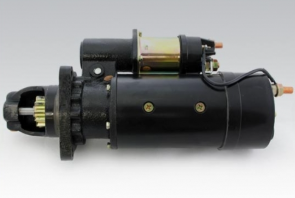
Starter for Detroit Diesel – Cummins, 12 Volts – RH – New
- Disconnect the negative and positive battery cables to eliminate the risk of accidental engine startup.
- Remove the battery completely if space is required for accessing certain components.
- Secure the Work Area:

Technician With Proper Eye & Ear Protection
- Ensure the engine is in a well-ventilated area.
- Use appropriate personal protective equipment (PPE), such as gloves, goggles, and steel-toed boots.
- Ensure that fire extinguishers are readily available due to the handling of flammable fluids like oil and fuel.
- Prepare Tools and Equipment:

Above is a picture of a parts cleaning and disassembly station. Tools for cleaning & disassembly are kept here for easy access during this part of the process.
- Gather all necessary tools, such as wrenches, sockets, drain pans, and lifting equipment.
- Inspect lifting devices like engine hoists or cranes for safety and functionality.
1.2. Draining Fluids
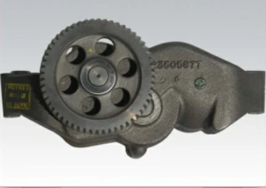
The engine must be drained of all fluids before disassembly to prevent spills and contamination.
- Drain Lubricating Oil:
- Place a suitable drain pan under the oil pan drain plug.
- Remove the drain plug using a wrench and allow the oil to drain completely.
- Inspect the oil for debris or metal shavings, which could indicate internal wear or damage.
- Replace the drain plug and torque to specifications to avoid leaks.
Oil Capacity:
- 11.1L: ~32 quarts
- 12.7L: ~38 quarts
- 14L: ~45 quarts
- Drain Coolant:
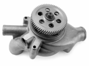
Water Pump, New, for Detroit 60 Series 11.1 and 12.7 lt engines.
- Open the cooling system drain plugs located on the oil cooler and cylinder block.
- Remove the radiator cap to relieve pressure and allow for smoother flow.
- Open thermostat housing drain cocks if applicable to ensure all coolant is removed.
- Collect coolant in a clean container for disposal or reuse if it meets quality standards.
- Flush the cooling system with clean water if contamination is suspected.
Coolant Capacity:
- 11.1L: ~48 quarts
- 12.7L: ~54 quarts
- 14L: ~60 quarts
- Drain Fuel System:

Fuel pump for Detroit Diesel series 60
- Place a container under the fuel lines to collect any residual fuel.
- Disconnect the fuel lines at the primary filter and cylinder head.
- Drain the fuel filter and inspect for signs of contamination or water.
- Remove the fuel filter if it requires replacement during the overhaul.
1.3. Additional Fluid-Handling Steps
- Transmission Fluid (if applicable):
- If the engine is connected to a transmission, disconnect the lines and drain any transmission fluid that may be circulating through the cooler.
- If the engine is connected to a transmission, disconnect the lines and drain any transmission fluid that may be circulating through the cooler.
- Power Steering Fluid (if applicable):
- Drain power steering fluid from the pump if the system is integrated with the engine.
- Drain power steering fluid from the pump if the system is integrated with the engine.
- Turbocharger Oil Lines:
- Disconnect and drain oil from turbocharger feed and return lines.
1.4. Removing Contaminants
- Clean the Exterior of the Engine:
- Use a degreaser to clean the engine exterior.
- Rinse thoroughly with a pressure washer or steam cleaner to remove grease, oil, and dirt.
- Allow the engine to dry completely to avoid introducing moisture during disassembly.
- Check for Leaks:
- Inspect the exterior for signs of leaks from gaskets, seals, or hoses.
- Mark areas of concern for closer inspection during disassembly.
1.5. Organizing the Workspace

- Set Up Engine Stand:
- Position the engine stand in a stable area with adequate space for maneuvering tools and components.
- Position the engine stand in a stable area with adequate space for maneuvering tools and components.
- Label and Store Parts:
- Prepare labeled containers or trays for storing bolts, fasteners, and small components.
- Use a tagging system to label hoses, lines, and electrical connectors for easier reassembly.
- Prepare Waste Disposal:
- Have designated containers for used oil, coolant, and fuel to ensure safe and environmentally compliant disposal.
1.6. Inspect the Engine for Preliminary Issues
- Visual Inspection:
- Check for obvious signs of wear, corrosion, or damage on external components.
- Note areas requiring special attention during the overhaul, such as worn belts or damaged hoses.
- Documentation:
- Record any issues observed during the preliminary inspection.
- Take photographs of the engine setup for reference during reassembly.
Step 2: Engine Removal For Detroit Diesel Series 60 Engines (11.1L, 12.7L, 14L)
The engine removal process is a critical stage in an overhaul, requiring careful disconnection of components and secure handling to prevent damage to the engine and surrounding systems. The following comprehensive guide ensures proper removal and handling of the engine.
2.1. Preparation for Engine Removal
- Ensure Safety:
- Verify that all fluids have been drained as per the preparation step.
- Wear appropriate personal protective equipment (PPE) such as gloves, goggles, and steel-toed boots.
- Ensure the workspace is clear of unnecessary tools or materials that could obstruct engine removal.
- Inspect Equipment:
- Confirm that the lifting device (e.g., engine hoist or crane) is in good working condition and has sufficient capacity to handle the engine’s weight.
- Prepare a dedicated overhaul stand, such as the J-29109, for engine placement after removal.
- Label Components:
- Use tags or labels to mark disconnected components such as hoses, wiring, and brackets to ensure easy reassembly.
2.2. Disconnecting Components
- Air System Components:
- Remove the air cleaner ducting from the intake manifold.
- Disconnect charge air cooler ducting between the turbocharger and intercooler.
- Inspect all hoses for wear or damage and set aside for replacement if needed.
- 11.1L: Uses smaller ducting, making removal simpler.
- 14L: Larger ducting and clamps require more clearance and additional disconnection points.
- Exhaust System:
- Detach the exhaust piping from the turbocharger.
- Remove exhaust brackets or hangers that may secure the exhaust system to the engine or frame.
- Inspect exhaust gaskets and flanges for damage and replace as necessary.
Note: The 14L turbocharger is larger and may include additional support brackets
- Cooling System:

Water Pump, New, for Detroit 60 Series 11.1 and 12.7 lt engines.
- Disconnect the coolant hoses from the radiator, water pump, and oil cooler.
- Remove the radiator and fan assembly by detaching the mounting brackets.
- Inspect the fan blades for cracks and ensure the radiator is free of leaks or blockages.
- 11.1L: Features smaller radiators and fewer hoses.
- 14L: Larger radiators and fan assemblies may include additional mounting brackets.
- Electrical Equipment:
- Remove the alternator by disconnecting the wiring harness and unbolting it from its mounting brackets.
- Disconnect the cranking motor cables, ensuring they are labeled for proper reinstallation.
- Inspect all electrical connections and cables for signs of wear or corrosion.
- Fuel System:

Fuel pump for Detroit Diesel series 60
- Detach fuel lines at the primary filter and injector pump.
- Cap or plug open fuel lines to prevent contamination.
- Remove the fuel filter housing if it obstructs access to other components.
2.3. Disconnecting the Engine from the Transmission
- Remove Bell Housing Bolts:
- Support the transmission with a jack or stand before removing the bolts securing the engine bell housing to the transmission.
- Support the transmission with a jack or stand before removing the bolts securing the engine bell housing to the transmission.
- Disconnect the Driveshaft:
- If necessary, remove the driveshaft to facilitate engine removal.
- If necessary, remove the driveshaft to facilitate engine removal.
- Inspect Mounts and Bolts:
- Examine engine and transmission mounts for wear or damage.
- Label and organize bolts and brackets for reassembly.
2.4. Securing and Lifting the Engine
- Attach the Lifting Device:
- Use the three engine lifting brackets located on the engine. Ensure the lifting device is securely fastened to each bracket.
- Confirm that the hoist or crane is rated for the weight of the engine.
- Verify Balance:
- Check the balance of the engine by slowly applying tension to the lifting device. Adjust lifting points if the engine tilts excessively.
- Check the balance of the engine by slowly applying tension to the lifting device. Adjust lifting points if the engine tilts excessively.
- Lift the Engine:
- Raise the engine slowly and steadily to avoid sudden movements or swaying.
- Monitor clearance as the engine is lifted to prevent damage to surrounding components.
- Place on Overhaul Stand:
- Position the engine securely on a dedicated overhaul stand, such as the J-29109.
- Ensure the engine is stabilized and locked into place before releasing the lifting device.
2.5. Inspect and Document
- Inspect Mounting Points:
- Check the engine mounts, lifting brackets, and bell housing for damage or wear during removal.
- Document any issues for repair or replacement during the overhaul process.
- 11.1L: Lighter mounts and simpler setup.
- 14L: Larger mounts and heavier transmission connections may require extra care.
- Organize Removed Components:
- Store removed components in labeled containers or on shelves for easy access during reassembly.
- Verify that all bolts, nuts, and brackets are accounted for and organized by component group.
- Clean Work Area:
- Remove any spilled fluids, debris, or tools from the workspace to maintain a safe and efficient environment for the next steps.
Key Tips for Successful Engine Removal
- Double-Check Disconnections: Ensure all connections are fully detached before lifting the engine to avoid damage to components or hoses.
- Maintain Alignment: Use alignment marks or tags to track the positions of critical components for accurate reassembly.
- Use Proper Equipment: Only use certified lifting devices and stands to handle the weight and size of the engine safely.
- Engine Weights:
- 11.1L: ~2,300 lbs.
- 12.7L: ~2,450 lbs.
- 14L: ~2,600 lbs.
Step 3: Disassembly For Detroit Diesel Series 60 Engines (11.1L, 12.7L, 14L)
The disassembly process is a crucial part of the overhaul procedure, requiring precision and organization to ensure all components are properly removed, inspected, and stored for reassembly. This expanded guide provides detailed instructions for disassembling the engine.
3.1. Remove the Valve Rocker Cover, Rocker Arm Shaft Assemblies, and Injectors
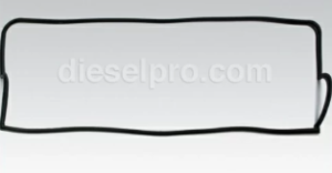
- Valve Rocker Cover:
- Loosen and remove the bolts securing the rocker cover.
- Carefully lift the cover to avoid damaging the gasket or cover itself.
- Inspect the gasket for wear or leaks and replace if necessary.
- Rocker Arm Shaft Assemblies:
- Loosen the rocker arm shaft bolts evenly in a cross pattern to prevent warping.
- Remove the rocker arms and shafts, keeping components organized for reassembly.
- Injectors:
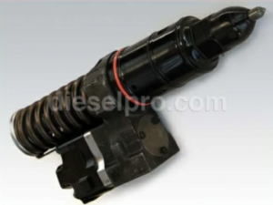
Injector for Detroit Diesel series 60 – rebuilt
- Disconnect the fuel lines from the injectors.
- Use an injector puller tool to carefully remove the injectors.
- Inspect the injector tips for carbon buildup or wear and replace if needed.
3.2. Detach the Camshaft Assembly
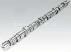
- Timing Gear Cover:
- Remove the bolts securing the timing gear cover to the engine block.
- Carefully pry off the cover to expose the camshaft gear and timing marks.
- Camshaft Gear:
- Mark the gear’s position relative to the timing marks to ensure proper alignment during reassembly.
- Use a gear puller to detach the camshaft gear without damaging adjacent components.
- Camshaft and Bearings:
- Loosen and remove the camshaft bearing caps.
- Carefully slide the camshaft out of the engine, supporting it to prevent damage to the journals or bearings.
- Inspect the bearings for wear, scoring, or pitting. Replace any damaged bearings.
3.3. Disassemble the Gear Train
- Idler Gears:
- Remove the bolts securing the idler gears and slide them off their shafts.
- Inspect the gears for wear, chipping, or misalignment.
- Bull Gear:
- Use a puller to remove the bull gear from the crankshaft.
- Inspect the teeth for damage and ensure the gear is within wear tolerances.
3.4. Remove Major Components
- Cylinder Head:
- Loosen the head bolts in a spiral pattern, working outward from the center to prevent warping.
- Lift the cylinder head using a lifting bracket or hoist to prevent injury or damage.
- Inspect the head for cracks, warping, or corrosion, and replace or machine as necessary.
- Flywheel and Flywheel Housing:
- Lock the flywheel in place using a flywheel locking tool.
- Remove the flywheel bolts and carefully detach the flywheel.
- Unbolt the flywheel housing and remove it from the engine.
- Inspect the flywheel surface for scoring or heat damage and replace if needed.
- Oil Pan and Oil Pump:
- Remove the oil pan bolts and lower the pan carefully to avoid spillage.
- Detach the oil pump by removing the securing bolts.
- Inspect the pump gears and housing for wear or damage. Replace as necessary.
- Pistons, Connecting Rods, and Crankshaft:
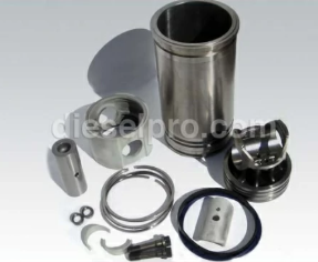
Clylinder Kit for Detroit Diesel Series 60 Engine
- Remove the connecting rod caps and push the pistons out of the cylinder bores.
- 11.1L: Shorter rods due to smaller displacement.
- 12.7L: Standard rod length.
- 14L: Longer and heavier rods to handle increased torque.Torque for Rod Bolts (Disassembly):
- 11.1L: 35–45 lb-ft.
- 12.7L: 45–55 lb-ft.
- 14L: 50–60 lb-ft.
-
Use a soft mallet to gently tap stubborn pistons free.
- Unbolt the main bearing caps and carefully lift the crankshaft from the engine block.
- Inspect the crankshaft journals for scoring or excessive wear.
- Remove the connecting rod caps and push the pistons out of the cylinder bores.
3.5. Remove Cylinder Liners
- Preparation:
- Inspect the liners for signs of scoring, pitting, or cavitation damage before removal.
- Clean the area around the top of the liners to prevent debris from falling into the block.
- Use the Liner Removal Tool (e.g., J-45876):
- Insert the tool into the cylinder liner and expand it to grip the liner securely.
- Use the puller to extract the liner evenly, avoiding tilting or damaging the liner seat in the block.
- Inspection:
- Examine the liner seats in the engine block for corrosion or damage. Clean thoroughly before installing new liners.
3.6. Organize and Inspect Components
- Label Components:
- Use tags or containers to label and store parts systematically.
- Group fasteners and small components by their respective assemblies for easier reassembly.
- Inspect Components:
- Perform a detailed inspection of all removed components, including gears, shafts, bearings, and seals.
- Record measurements for wear tolerances and note any parts requiring replacement.
Key Tips for Successful Disassembly
- Follow a Sequence: Work methodically to avoid missing components or causing damage.
- Maintain Cleanliness: Keep the work area clean to prevent debris from contaminating components.
- Use Proper Tools: Always use the appropriate tools, such as pullers and locking devices, to prevent damage to parts.
- Document as You Go: Take photos or notes during disassembly to assist during reassembly.
Step 4: Cleaning For Detroit Diesel Series 60 Engines (11.1L, 12.7L, 14L)
Cleaning the engine components is a crucial step in the overhaul process, as it ensures the removal of dirt, grease, carbon deposits, and contaminants that can compromise the integrity and performance of the engine. Proper cleaning also prepares the components for accurate inspection and reassembly.
4.1. Preparation for Cleaning
- Safety First:

Technician With Proper Eye & Ear Protection
- Wear appropriate personal protective equipment (PPE), including gloves, goggles, and a face mask, to protect against chemical exposure and debris.
- Work in a well-ventilated area to avoid inhaling fumes from cleaning solutions or steam.
- Set Up Cleaning Equipment:
- Prepare tools such as wire brushes, scrapers, degreasers, and cleaning tanks.
- Ensure cleaning tanks or containers are large enough to fully submerge engine components.
- Have a high-pressure washer or steam cleaner ready for final rinsing.
- Organize Components:
- Separate parts by material type (e.g., cast iron, aluminum, steel) to prevent chemical damage.
- Label and store small components securely to avoid loss during the cleaning process.
4.2. Cleaning Cast-Iron Parts
- Hot Alkaline Solution Cleaning:
- Submerge cast-iron components, such as the cylinder block and cylinder head, in a hot alkaline cleaning solution.
- Allow the parts to soak for the recommended time, typically 15–30 minutes, depending on the level of contamination.
- Agitate the solution or gently scrub with a brush to loosen stubborn grease and dirt.
- Inspection After Cleaning:
- Inspect the parts for any remaining residue. Repeat the cleaning process if necessary.
- Use a scraper or wire brush to remove carbon deposits from combustion chambers or valve ports.
4.3. Cleaning Water Jackets
- Scale and Rust Removal:
- For heavily scaled water jackets, prepare an inhibited phosphoric acid solution according to the manufacturer’s instructions.
- Immerse the cylinder block in the solution, ensuring the acid reaches all internal passages.
- Monitoring the Process:
- Watch for bubbling, which indicates the acid is dissolving scale and rust.
- Limit immersion time to prevent excessive material removal or damage to the block.
- Neutralization and Rinse:
- After removing the block from the acid, neutralize the acid with an alkaline solution.
- Thoroughly rinse the block with water or steam to remove all traces of the acid and neutralizing agent.
4.4. Degreasing Aluminum and Steel Components
- Use Non-Corrosive Cleaners:
- For aluminum parts such as pistons or oil pans, use a mild degreaser to avoid pitting or discoloration.
- Apply the cleaner with a brush or soak the parts in a degreasing tank.
- Rinse and Dry:
- Rinse parts thoroughly with water to remove degreaser residue.
- Use compressed air to dry parts completely, paying special attention to tight spaces where moisture can accumulate.
4.5. Cleaning Fuel and Lubrication System Components
- Fuel Injectors and Lines:
- Soak injectors and fuel lines in a cleaning solvent.
- Use a small brush to remove carbon deposits from injector tips.
- Oil Pump and Passages:
- Flush oil passages with a solvent to remove sludge and debris.
- Disassemble the oil pump if necessary to clean internal components thoroughly.
4.6. Cleaning Bearings and Journals
- Use Solvents for Delicate Components:
- Bearings, bushings, and journals should be cleaned with a non-abrasive solvent to avoid scratching or pitting.
- Bearings, bushings, and journals should be cleaned with a non-abrasive solvent to avoid scratching or pitting.
- Dry and Lubricate Immediately:
- Use compressed air to dry bearings and journals quickly. Apply a light coat of engine oil to protect against corrosion during storage.
4.7. Final Rinse and Steam Cleaning
- Steam Cleaning:
- Use a high-pressure steam cleaner to rinse large components such as the cylinder block and cylinder head.
- Focus on internal passages, including oil galleries and coolant channels, to ensure they are free of debris and contaminants.
- Inspect for Residual Debris:
- After cleaning, inspect all parts for leftover grease, carbon, or rust. Repeat cleaning steps if necessary.
- After cleaning, inspect all parts for leftover grease, carbon, or rust. Repeat cleaning steps if necessary.
- Drying Components:
- Use compressed air to dry components thoroughly, ensuring no moisture remains in internal passages or crevices.
- Store cleaned components in a dry, dust-free area to prevent contamination before reassembly.
4.8. Inspection During Cleaning
- Look for Cracks or Damage:
- Cleaning often reveals cracks, pitting, or other damage that may not have been visible earlier.
- Mark damaged areas for repair or replacement.
- Verify Internal Passages:
- Ensure all oil and coolant passages are clear and unobstructed. Use a probe or bore brush if necessary to remove stubborn blockages.
Key Tips for Effective Cleaning
- Follow Manufacturer Guidelines: Use cleaning agents and procedures specified for the Detroit Diesel Series 60 engine to avoid damaging components.
- Neutralize Acidic Solutions: Always neutralize acid solutions thoroughly to prevent residual corrosion.
- Avoid Abrasives on Precision Surfaces: Do not use wire brushes or abrasive pads on surfaces like journals, bearings, or piston crowns.
Step 5: Inspection For Detroit Diesel Series 60 Engines (11.1L, 12.7L, 14L)
Inspection is a critical step in the overhaul process, ensuring that all engine components meet the required standards for reuse or replacement. Detailed inspection prevents premature failure and ensures optimal performance after reassembly. Below is a comprehensive guide for inspecting key engine components.
5.1. Tools and Equipment Required

- Micrometers (inside and outside)
- Dial indicator with magnetic base
- Plastigage strips
- Bore gauges
- Straightedges and feeler gauges
- Cleaning cloths
- Visual inspection tools (magnifying glass, flashlight)
- Manufacturer’s specifications for tolerances and wear limits
5.2. Inspection of Components
Pistons

- Visual Inspection:
- Look for cracks in the piston crown, skirt, or pin bosses.
- Examine the piston surface for scoring caused by debris or lubrication failure.
- Check for signs of overheating, such as discoloration or distortion.
- Ring Grooves:
- Inspect grooves for excessive wear that could prevent proper ring seating.
- Measure groove depth and width to ensure compatibility with new piston rings.
- Piston Skirt:
- Check for wear patterns indicating improper alignment or excessive side thrust.
- Check for wear patterns indicating improper alignment or excessive side thrust.
- Piston Pin and Bore:
- Measure the diameter of the piston pin and the bore to ensure proper fit.
- Inspect for looseness or wear that may indicate alignment issues.
Crankshaft
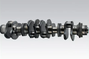
- Journals:
- Inspect all main and rod bearing journals for scoring, scratches, or excessive wear.
- Measure the diameter of journals using a micrometer at multiple points to check for out-of-round conditions.
- Runout:
- Mount the crankshaft in a lathe or support it on V-blocks. Use a dial indicator to measure runout at the center of the crankshaft.
- Acceptable runout typically does not exceed 0.002 inches.
- Keyways and Threads:
- Inspect the keyways for wear or cracks.
- Ensure threads for flywheel bolts and pulleys are clean and undamaged.
Cylinder Liners

- Surface Inspection:
- Check the liner bore for scoring, pitting, or cavitation erosion.
- Inspect for cracks along the length of the liner.
- Measure Bore Diameter:
- Use a bore gauge to measure the cylinder diameter at multiple points along the liner.
- Check for taper or out-of-round conditions by comparing measurements at the top, middle, and bottom of the liner.
- Liner Seats and Seals:
- Inspect the liner seat in the engine block for corrosion or wear.
- Check the liner seals for damage or deformation.
Bearings
- Visual Inspection:
- Examine main and rod bearings for scoring, spalling, or pitting.
- Look for signs of overheating, such as discoloration or melted surfaces.
- Clearance Measurement:
- Use plastigage to measure the clearance between the bearings and the journals.
- Compare the measured clearance to manufacturer specifications, typically 0.001–0.003 inches for main and rod bearings.
Connecting Rods
- Visual Inspection:
- Check for cracks, particularly at the small and big ends.
- Inspect for bending or twisting using a straightedge or specialized tool.
- Bushing Fit:
- Inspect the small-end bushing for wear or damage.
- Measure the bore diameter to ensure the correct fit for the piston pin.
- Big-End Bore:
- Measure the big-end bore diameter and compare it to specifications. Replace rods if out of tolerance.
Camshaft and Valve Train Components
- Camshaft:
- Inspect camshaft lobes for pitting, scoring, or flattening.
- Measure lobe height to verify it meets manufacturer tolerances.
- Check the journals for wear or scoring.
- Camshaft Bearings:
- Inspect bearings for excessive wear or pitting. Replace if clearances exceed specified limits.
- Rocker Arms and Pushrods:
- Inspect for signs of bending, cracks, or wear.
- Roll pushrods on a flat surface to check for straightness.
Additional Components
- Oil Pump:
- Inspect the pump gears for wear, scoring, or binding.
- Measure the clearance between the gears and housing to ensure proper operation.
- Timing Gears:
- Check for chipped teeth or uneven wear.
- Inspect gear lash with a dial indicator and ensure it meets the specified range.
- Gaskets and Seals:
- Examine all seals and gaskets for cracks, deformation, or wear. Replace them during reassembly.
5.3. Measurement Techniques
- Using Micrometers:
- Measure diameters of journals, bores, and pistons.
- Take measurements at multiple points to identify taper or ovality.
- Using Plastigage:
- Place a strip of plastigage on the journal, install the bearing cap, and torque to specifications.
- Remove the cap and measure the flattened strip with the provided gauge.
- Bore Gauges and Feeler Gauges:
- Use a bore gauge for cylinder liners and connecting rod big ends.
- Use feeler gauges to measure clearances, such as valve lash and liner protrusion.
5.4. Compare Measurements to Manufacturer Specifications
This section provides the specific tolerances and wear limits for critical engine components to ensure proper function and durability. Measurements exceeding these limits indicate the need for replacement or repair. All measurements should be taken using precision tools like micrometers, bore gauges, and plastigage. Below are the detailed specifications for key components.
Component |
Instruction for Measurement |
11.1L Standard |
11.1L Wear Limit |
12.7L Standard |
12.7L Wear Limit |
14L Standard |
14L Wear Limit |
|---|---|---|---|---|---|---|---|
Piston |
|||||||
| Diameter | Measure at the skirt perpendicular to the wrist pin using a micrometer. | 4.921–4.922 in | 4.919 in | 4.921–4.927 in | 4.919 in | 5.118–5.120 in | 5.116 in |
| Ring End Gap (Top/Compression) | Insert ring into the liner, square it with a piston, and measure the gap with a feeler gauge. | 0.010–0.020 in | 0.025 in | 0.010–0.020 in | 0.025 in | 0.012–0.025 in | 0.030 in |
| Ring Side Clearance | Place the ring into its groove and use a feeler gauge to measure clearance between the ring and groove. | 0.0016–0.0028 in | 0.0030 in | 0.0016–0.0028 in | 0.0030 in | 0.0018–0.0030 in | 0.0035 in |
Cylinder Liner |
|||||||
| Bore Diameter | Measure at the top, middle, and bottom of the bore with a bore gauge. Take readings at 90° angles. | 4.925–4.927 in | 4.935 in | 4.925–4.927 in | 4.935 in | 5.122–5.124 in | 5.134 in |
| Liner Protrusion Above Block | Use a straightedge and feeler gauge or a dial indicator to measure liner height relative to the block deck. | 0.001–0.004 in | 0.000 in or >0.004 in | 0.001–0.004 in | 0.000 in or >0.004 in | 0.001–0.005 in | 0.000 in or >0.005 in |
| Out-of-Round (Max) | Compare readings from the bore at 0° and 90° to identify differences. | 0.002 in | 0.002 in | 0.002 in | 0.002 in | 0.003 in | 0.003 in |
| Taper (Max) | Subtract the bottom bore measurement from the top to determine taper. | 0.002 in | 0.002 in | 0.002 in | 0.002 in | 0.003 in | 0.003 in |
Crankshaft |
|||||||
| Main Journal Diameter | Measure diameter at multiple points using a micrometer. Check for taper or out-of-round. | 3.186–3.188 in | 3.184 in | 3.186–3.188 in | 3.184 in | 3.425–3.427 in | 3.423 in |
| Rod Journal Diameter | Measure diameter at multiple points using a micrometer. | 2.998–3.000 in | 2.996 in | 2.998–3.000 in | 2.996 in | 3.346–3.348 in | 3.344 in |
| Main Bearing Clearance | Place plastigage on the journal, install the bearing, and torque the cap to spec. Measure the squished plastigage width with the gauge provided. | 0.002–0.003 in | 0.004 in | 0.002–0.003 in | 0.004 in | 0.002–0.004 in | 0.005 in |
| Rod Bearing Clearance | Perform the same procedure as for main bearings. | 0.001–0.003 in | 0.004 in | 0.001–0.003 in | 0.004 in | 0.002–0.004 in | 0.005 in |
| Crankshaft Runout (Max) | Support the crankshaft on V-blocks and measure runout with a dial indicator at the center journal. | 0.002 in | 0.003 in | 0.002 in | 0.003 in | 0.004 in | 0.005 in |
| End Play | Measure movement of the crankshaft with a dial indicator while pushing it forward and backward. | 0.002–0.006 in | 0.008 in | 0.002–0.006 in | 0.008 in | 0.002–0.008 in | 0.010 in |
Connecting Rods |
|||||||
| Big-End Bore Diameter | Use an inside micrometer to measure the bore diameter at 90° intervals. | 3.188–3.190 in | 3.192 in | 3.188–3.190 in | 3.192 in | 3.350–3.352 in | 3.354 in |
| Small-End Bushing Diameter | Measure the internal diameter of the small-end bushing with an inside micrometer. | 1.653–1.655 in | 1.657 in | 1.653–1.655 in | 1.657 in | 1.900–1.902 in | 1.904 in |
| Side Clearance | Measure clearance between the rod and crankshaft using a feeler gauge. | 0.010–0.020 in | 0.030 in | 0.010–0.020 in | 0.030 in | 0.015–0.030 in | 0.040 in |
Valve Train |
|||||||
| Valve Stem-to-Guide Clearance | Insert a feeler gauge between the valve stem and the guide to measure clearance. | Intake: 0.001–0.003 in | 0.005 in | Intake: 0.002–0.004 in | 0.006 in | Intake: 0.002–0.004 in | 0.006 in |
| Exhaust: 0.002–0.004 in | 0.006 in | Exhaust: 0.003–0.005 in | 0.007 in | Exhaust: 0.003–0.005 in | 0.007 in |
Component |
Instruction for Measurement |
11.1L Standard |
11.1L Wear Limit |
12.7L Standard |
12.7L Wear Limit |
14L Standard |
14L Wear Limit |
|---|---|---|---|---|---|---|---|
Gear Train |
|||||||
| Gear Lash | Use a dial indicator on the teeth of the mating gears. Rotate the driven gear back and forth and record the total movement. | 0.002–0.009 in | 0.010 in | 0.002–0.009 in | 0.010 in | 0.002–0.009 in | 0.010 in |
| Timing Gear Runout (Max) | Mount a dial indicator to the gear housing. Rotate the gear and measure the maximum deflection at the outer edge of the gear. | 0.002 in | 0.004 in | 0.002 in | 0.004 in | 0.004 in | 0.005 in |
| Idler Gear End Play | Use a feeler gauge to measure the clearance between the gear face and the housing when the gear is pushed against the shaft. | 0.002–0.006 in | 0.008 in | 0.002–0.006 in | 0.008 in | 0.002–0.008 in | 0.010 in |
| Bull Gear End Play | Measure clearance between the bull gear and the housing using a feeler gauge. | 0.004–0.010 in | 0.012 in | 0.004–0.010 in | 0.012 in | 0.006–0.012 in | 0.015 in |
| Camshaft Gear-to-Idler Gear Lash | Measure with a dial indicator positioned on the camshaft gear. Rotate the idler gear back and forth to determine lash. | 0.002–0.006 in | 0.008 in | 0.002–0.006 in | 0.008 in | 0.002–0.008 in | 0.010 in |
Additional Components |
|||||||
| Turbocharger Shaft End Play | Use a dial indicator to measure axial movement of the turbocharger shaft. | 0.002–0.005 in | 0.006 in | 0.002–0.005 in | 0.006 in | 0.002–0.005 in | 0.007 in |
| Turbocharger Shaft Radial Play | Measure radial movement of the turbocharger shaft using a dial indicator on the compressor or turbine wheel. | 0.001–0.003 in | 0.004 in | 0.001–0.003 in | 0.004 in | 0.001–0.003 in | 0.005 in |
Action Plan for Out-of-Spec Measurements
- Document Findings:
- Record all measurements and highlight those exceeding allowable limits.
- Record all measurements and highlight those exceeding allowable limits.
- Replace Components:
- Replace any components that do not meet the specified tolerances. Use new gaskets, seals, and fasteners as required.
- Replace any components that do not meet the specified tolerances. Use new gaskets, seals, and fasteners as required.
- Reinspect Critical Areas:
- After replacing components, remeasure to verify compliance with specifications.
5.5. Documentation and Marking
- Label Components:
- Mark components that need replacement or rework. Use tags or paint markers for clear identification.
- Mark components that need replacement or rework. Use tags or paint markers for clear identification.
- Create an Inspection Report:
- Record all measurements and findings in an organized format for reference during reassembly.
Step 6: Replacement For Detroit Diesel Series 60 Engines (11.1L, 12.7L, 14L)
The replacement of worn or damaged components during an engine overhaul is essential to ensure reliability, performance, and longevity. Any part that fails inspection or is found to be out of specification must be replaced to prevent operational failures or additional maintenance issues post-overhaul.
6.1. Replacement of Cracked or Worn Pistons and Liners

Pistons
- Replacement Criteria:
- Replace pistons with visible cracks, scoring, or excessive wear.
- Replace pistons if they do not meet dimensional tolerances for diameter, ring groove clearance, or pin bore size.
- Selection of Replacement Pistons:
- Use pistons that match the original part in size, material, and weight to maintain engine balance.
- For oversized or undersized applications, verify compatibility with the cylinder liners and crankshaft journals.
- Preassembly Steps:
- Thoroughly clean replacement pistons to remove any protective coatings.
- Install new piston rings, ensuring they are correctly gapped and seated.
- Apply assembly lubricant to the piston skirts, pin bores, and rings before installation.
Cylinder Liners
- Replacement Criteria:
- Replace liners that exhibit pitting, scoring, cracks, or out-of-round conditions.
- Replace liners with excessive taper or wear, exceeding manufacturer-specified tolerances.
- Installing New Liners:
- Clean the Liner Seats: Remove all debris, corrosion, and old sealant from the liner seats in the engine block.
- Install New Seals: Coat the liner seals with a light layer of lubricant to ensure proper seating and leak prevention.
- Check Protrusion: Use a dial indicator to measure liner protrusion above the deck. Verify that the protrusion is within specified limits to ensure proper sealing with the cylinder head gasket.
- Final Inspection:
- Rotate the crankshaft manually after installation to confirm the liner’s alignment and clearance with the piston.
6.2. Replacement of Worn Bearings and Bushings
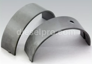
Bearings
- Replacement Criteria:
- Replace bearings showing scoring, pitting, spalling, or uneven wear patterns.
- Bearings with excessive clearance beyond manufacturer tolerances must be replaced.
- Selection of Replacement Bearings:
- Use bearings of the correct size and material to match the crankshaft and engine specifications.
- For reconditioned crankshafts, ensure the bearings match the regrind dimensions (e.g., undersized bearings).
- Installation Steps:
- Clean bearing surfaces and apply a thin layer of assembly lubricant.
- Install bearings into their housings, ensuring they are fully seated and aligned.
- Measure bearing clearances using plastigage or a micrometer to confirm they meet manufacturer tolerances.
Bushings
- Replacement Criteria:
- Replace bushings in connecting rods or small ends that show ovalization, scoring, or excessive wear.
- Replace camshaft bushings with visible pitting, wear, or loose fits.
- Installation of New Bushings:
- Use a press or specialized tools to install bushings evenly without distortion.
- Verify the internal diameter of the installed bushing meets specifications for the mating component.
- Apply assembly lube to the bushing surface before reassembly.
6.3. Replacement of Crankshaft or Cylinder Block

Crankshaft
- Replacement Criteria:
- Replace the crankshaft if journals exhibit deep scoring, cracks, or out-of-round conditions beyond allowable regrind limits.
- Replace the crankshaft if runout exceeds specifications or if it is damaged by stress fractures.
- Selection of Replacement Crankshaft:
- Use an OEM-equivalent or premium aftermarket crankshaft that matches the engine’s original specifications.
- For engines requiring a reconditioned crankshaft, ensure the journals are properly reground and polished.
- Installation of New Crankshaft:
- Install new main bearings and thrust washers.
- Align the crankshaft carefully to prevent binding or misalignment.
- Torque main caps to manufacturer specifications, ensuring even pressure.
Main Bearings and Caps:
- Torque Specifications:
- 11.1L: 135 lb-ft, plus 90°.
- 12.7L: 150 lb-ft, plus 90°.
- 14L: 175 lb-ft, plus 90°.
- Torque Specifications:
Cylinder Block
- Replacement Criteria:
- Replace the cylinder block if it exhibits cracks, excessive corrosion, or warping beyond repairable limits.
- Replace the block if liner seats or bearing saddles are irreparably damaged or misaligned.
- Selection of Replacement Block:
- Use a replacement block that matches the original specifications, including bore size and mounting dimensions.
- Installation Preparation:
- Ensure all mating surfaces are clean and free of debris.
- Transfer components such as oil galleries, plugs, and coolant passages from the old block if applicable.
- Verify proper alignment of the block with the crankshaft and timing components during reassembly.
6.4. Best Practices for Replacement
- Replace Gaskets and Seals:
- Always install new gaskets and seals during reassembly to prevent leaks and ensure proper sealing.
- Use Quality Components:
- Use OEM-equivalent or high-quality aftermarket components for all replacements to ensure durability and performance.
- Verify Compatibility:
- Double-check part numbers and specifications to ensure compatibility with your engine’s variant.
- Follow Torque Specifications:
- Use a calibrated torque wrench to secure all replacement components according to manufacturer specifications.
- Document Replacements:
- Keep records of all replaced parts, including part numbers and specifications, for future maintenance or troubleshooting.
Step 7: Reassembly For Detroit Diesel Series 60 Engines (11.1L, 12.7L, 14L)
Reassembly is the final step in the engine overhaul process. It requires precision, adherence to torque specifications, and careful handling of all components. Proper installation ensures optimal performance and engine longevity.
Step 7.1: Install Bearings and Crankshaft For Detroit Diesel Series 60 Engines (11.1L, 12.7L, 14L)
Reassembling the bearings and crankshaft is a critical step in ensuring the engine’s structural integrity and smooth operation. The procedure must be followed precisely, with specific torque values tailored for each engine type.
Prepare Bearings
- Clean the Bearing Surfaces:
- Thoroughly clean the bearing saddles and caps to remove oil residue, dirt, or debris that could cause uneven seating or premature wear.
- Apply Assembly Lubricant:
- Apply a thin, even layer of assembly lubricant to the back of the bearings and journal surfaces to minimize friction during initial operation.
Install Main Bearings
- Position Bearings in the Saddles:
- Place the main bearings into the block saddles and caps, ensuring the locating tabs align properly with the notches.
- Install Thrust Bearings:
- Position thrust bearings on the designated journal (usually the rear main journal). Ensure the thrust faces are oriented to handle axial loads.
Install the Crankshaft
- Lower the Crankshaft into Position:
- Carefully lower the crankshaft into the block using an engine hoist if necessary. Ensure it rests evenly on the bearings without binding.
- Verify Alignment:
- Rotate the crankshaft gently by hand to confirm smooth movement and proper seating on the bearings.
Secure the Crankshaft with Main Caps
- Install Main Caps:
- Place the main caps over the crankshaft journals, ensuring they are oriented correctly based on any identification marks.
- Place the main caps over the crankshaft journals, ensuring they are oriented correctly based on any identification marks.
- Torque the Main Cap Bolts:
- Tighten bolts in three stages according to engine size:
- 11.1L:
- Stage 1: Tighten to 135 lb-ft (183 Nm).
- Stage 2: Tighten to 270 lb-ft (366 Nm).
- Final Stage: Turn an additional 90 degrees.
- 12.7L:
- Stage 1: Tighten to 150 lb-ft (203 Nm).
- Stage 2: Tighten to 300 lb-ft (407 Nm).
- Final Stage: Turn an additional 90 degrees.
- 14L:
- Stage 1: Tighten to 175 lb-ft (237 Nm).
- Stage 2: Tighten to 325 lb-ft (441 Nm).
- Final Stage: Turn an additional 90 degrees.
- 11.1L:
- Tighten bolts in three stages according to engine size:
Verify Crankshaft End Play
- Measure End Play:
- Use a dial indicator mounted on the block to measure crankshaft end play.
- Acceptable Range:
- Ensure end play is within 0.002–0.006 in (0.05–0.15 mm) for all engine sizes.
- Adjust as Needed:
- If end play exceeds the limit, verify thrust bearing installation or replace worn components.
Summary of Key Adjustments
- Torque Values vary by engine size, reflecting differences in bolt diameter and loading requirements.
- Thrust Bearing Orientation is critical for proper axial load handling.
- End Play Verification ensures the crankshaft can move freely without binding or excessive movement.
Step 7.2: Install Pistons and Connecting Rods For Detroit Diesel Series 60 Engines (11.1L, 12.7L, 14L)
Proper installation of pistons and connecting rods is vital for engine performance and longevity. This step requires precise handling, correct alignment, and adherence to torque specifications tailored to each engine size.
Prepare Pistons
- Attach Connecting Rods:
- Connect the rods to the pistons using new wrist pins and retaining clips. Ensure that the rods are oriented correctly for proper installation.
- Connect the rods to the pistons using new wrist pins and retaining clips. Ensure that the rods are oriented correctly for proper installation.
- Inspect and Install Piston Rings:
- Verify that the piston rings are properly installed in their respective grooves.
- Stagger the ring gaps at 120° intervals around the piston to prevent compression loss.
- Apply Lubricant:
- Coat the piston rings, skirts, and pin bores with assembly lubricant to reduce friction during installation and initial operation.
Use a Ring Compressor
- Compress Piston Rings:
- Use a high-quality ring compressor to compress the piston rings evenly around the piston.
- Insert Piston into Liner:
- Carefully slide the piston into the cylinder liner, ensuring proper alignment with the connecting rod.
- Push the piston until the skirt clears the liner without forcing it.
Attach Connecting Rod Caps
- Align Connecting Rods:
- Rotate the crankshaft to position the appropriate journal for rod installation.
- Align the connecting rod with the crankshaft journal.
- Install New Rod Bolts:
- Insert and hand-tighten new bolts to hold the rod cap in place.
- Insert and hand-tighten new bolts to hold the rod cap in place.
- Torque Specifications:
- Tighten bolts in two stages according to engine size:
- 11.1L:
- Stage 1: Tighten to 35 lb-ft (47 Nm).
- Final Stage: Turn an additional 90 degrees.
- 12.7L:
- Stage 1: Tighten to 45 lb-ft (61 Nm).
- Final Stage: Turn an additional 90 degrees.
- 14L:
- Stage 1: Tighten to 50 lb-ft (68 Nm).
- Final Stage: Turn an additional 90 degrees.
- 11.1L:
- Tighten bolts in two stages according to engine size:
Verify Movement
- Rotate the Crankshaft:
- Manually rotate the crankshaft after installing each piston to ensure smooth movement.
- Check for Binding or Resistance:
- If binding is detected, verify the alignment of the connecting rod and journal.
- Repeat for Remaining Pistons:
- Repeat the installation process for all pistons, following the firing order of the engine to streamline assembly.
Summary of Key Adjustments
- Torque Values: Specific to each engine size due to differences in rod design and stress requirements.
- Piston Ring Staggering: Prevents blow-by and improves compression efficiency.
- Crankshaft Rotation: Verifies proper assembly and ensures no interference or binding.
Step 7.3: Install Camshaft and Gear Train For Detroit Diesel Series 60 Engines (11.1L, 12.7L, 14L)
Lubricate Camshaft
- Apply a liberal coat of assembly lubricant to all camshaft journals and lobes to minimize wear during initial startup.
- Ensure that the lubricant covers all contact surfaces, including the camshaft bearing seats.
Install the Camshaft
- Carefully slide the camshaft into the engine block, supporting it to prevent damage to the bearings.
- Rotate the camshaft slightly as it is installed to ensure smooth engagement with the bearings.
- Verify that the camshaft rotates freely once installed.
Install Timing Gears
- Align the timing marks:
- Crankshaft Gear: Ensure the mark aligns with the corresponding mark on the idler gear.
- Camshaft Gear: Align the mark with the idler gear timing mark.
- Idler Gear: Ensure alignment with both the camshaft and crankshaft gears.
- Torque Specifications for Camshaft Gear Retaining Bolt:
- All Sizes: Tighten to 200 lb-ft (271 Nm).
- All Sizes: Tighten to 200 lb-ft (271 Nm).
- Measure Gear Lash:
- Position a dial indicator on the camshaft gear and measure the lash between the camshaft gear and idler gear.
- Acceptable range: 0.002–0.009 in (0.051–0.229 mm).
- If lash exceeds the limit, adjust by adding or removing shims.
Step 7.4: Install Cylinder Liners For Detroit Diesel Series 60 Engines (11.1L, 12.7L, 14L)
Prepare Liner Seats
- Clean the liner seats in the block thoroughly to remove debris, oil, and old seal material.
- Inspect the seats for cracks, scoring, or corrosion. Repair or replace the block if damage is beyond acceptable limits.
- Lubricate the O-ring grooves with clean engine oil to facilitate liner installation and prevent damage to seals.
Install New Seals
- Fit new O-rings onto the liners, ensuring they are correctly seated in the grooves.
- Apply a thin coat of clean oil or assembly lubricant to the O-rings to reduce friction during installation.
Insert Liners
- Lower each liner into the block using a liner installation tool to avoid damage.
- Ensure the liner seats firmly without tilting. Tap lightly with a rubber mallet if necessary to seat the liner fully.
Verify Liner Protrusion
- Measure liner protrusion using a dial gauge positioned across the liner and engine block deck.
- Acceptable Protrusion Ranges:
- 11.1L and 12.7L: 0.001–0.004 in (0.025–0.102 mm).
- 14L: 0.001–0.005 in (0.025–0.127 mm).
- Adjust or replace liners if protrusion is out of range to ensure proper sealing with the cylinder head gasket.
Step 7.5: Install Cylinder Head For Detroit Diesel Series 60 Engines (11.1L, 12.7L, 14L)
Prepare the Cylinder Head
- Clean the mating surfaces of the cylinder head and engine block to remove debris, oil, or old gasket material.
- Inspect the head for cracks, warping, or damage. Replace the head if it exceeds acceptable warpage limits:
- 11.1L and 12.7L: 0.002 in (0.05 mm).
- 14L: 0.003 in (0.08 mm).
- Place a new head gasket onto the block, aligning it with the dowel pins.
Position and Secure the Cylinder Head
- Lower the cylinder head carefully onto the block, ensuring alignment with the gasket and dowel pins.
- Hand-tighten the cylinder head bolts to hold the head in place.
Torque Cylinder Head Bolts
- Torque the bolts in three stages following the correct sequence:
- 11.1L:
- Stage 1: Tighten to 180 lb-ft (244 Nm).
- Stage 2: Tighten to 240 lb-ft (325 Nm).
- Final Stage: Turn an additional 90 degrees.
- 12.7L:
- Stage 1: Tighten to 200 lb-ft (271 Nm).
- Stage 2: Tighten to 300 lb-ft (407 Nm).
- Final Stage: Turn an additional 90 degrees.
- 14L:
- Stage 1: Tighten to 220 lb-ft (298 Nm).
- Stage 2: Tighten to 325 lb-ft (441 Nm).
- Final Stage: Turn an additional 90 degrees.
- 11.1L:
Step 7.6: Install Oil Pump and Oil Pan For Detroit Diesel Series 60 Engines (11.1L, 12.7L, 14L)
Oil Pump
- Mount the oil pump in its designated position and secure it with bolts.
- Torque Specifications for Oil Pump Bolts:
- All Sizes: 30–38 lb-ft (41–51 Nm).
Oil Pan
- Install a new gasket for the oil pan.
- Secure the oil pan with bolts, tightening them in a crisscross pattern.
- Torque Specifications for Oil Pan Bolts:
- All Sizes: 18–22 lb-ft (24–30 Nm).
Step 7.7: Reconnect Accessories For Detroit Diesel Series 60 Engines (11.1L, 12.7L, 14L)
Flywheel and Flywheel Housing
- Attach the flywheel housing and secure it with bolts:
- Torque Specification: 75 lb-ft (102 Nm).
- Install the flywheel and torque the bolts to:
- Torque Specification: 245 lb-ft (332 Nm).
Other Accessories
- Reinstall ancillary components such as:
- Alternator.
- Air compressor.
- Coolant pump.
- Reattach electrical wiring, coolant hoses, and fuel lines. Verify proper connections to avoid leaks or electrical faults.
Step 8: Final Checks For Detroit Diesel Series 60 Engines (11.1L, 12.7L, 14L)
The final checks ensure that the engine is properly assembled, all components are functioning as intended, and the engine is ready for operation. This critical phase verifies smooth mechanical operation, proper fluid flow, and the absence of leaks or misalignments. Below is a detailed guide to performing the final checks for the Detroit Diesel Series 60 engine.
8.1. Rotate the Crankshaft Manually
- Purpose:
- To ensure the engine’s internal components, such as pistons, connecting rods, crankshaft, and valves, move freely without interference or binding.
- To ensure the engine’s internal components, such as pistons, connecting rods, crankshaft, and valves, move freely without interference or binding.
- Procedure:
- Attach a suitable breaker bar to the crankshaft pulley bolt.
- Rotate the crankshaft through at least two complete revolutions (720 degrees) to simulate a full engine cycle.
- Pay close attention to resistance or unusual noises, which could indicate misaligned components, insufficient clearances, or improper installation.
- Common Issues to Check:
- Binding or resistance: May indicate interference between pistons and valves.
- Clicking or grinding noises: Suggest gear train misalignment or debris in the system.
- Corrective Action:
- If resistance or abnormal sounds are detected, disassemble and inspect the affected area to identify and resolve the issue before proceeding.
8.2. Perform a Dynamometer Run-In
A dynamometer (dyno) run-in is essential to ensure proper break-in of components, check for leaks, and verify engine timing and performance.
- Purpose:
- To simulate engine operation under controlled conditions.
- To measure power output, timing accuracy, and efficiency while monitoring for leaks or mechanical issues.
- Preparation:
- Secure the engine on a dynamometer test stand.
- Refill the engine with clean oil and coolant. Use break-in oil if recommended by the manufacturer.
- Connect all required sensors, including those for oil pressure, temperature, and exhaust emissions.
- Start-Up Procedure:
- Prime the oil system by cranking the engine without fuel injection to ensure oil circulation.
- Start the engine and let it idle at low RPM (typically 600–800 RPM) for 5–10 minutes to stabilize temperatures and pressures.
- Testing Procedure:
- Gradually increase engine speed and load in increments, monitoring for:
- Oil pressure: Should meet manufacturer specifications (typically 40–60 psi at operating temperature).
- Coolant temperature: Should stabilize within the specified range, typically 180–210°F (82–99°C).
- Exhaust color: Watch for excessive smoke, which could indicate timing issues or incomplete combustion.
- Leaks: Inspect all gaskets, seals, and fluid connections for signs of leakage.
- Perform multiple power runs at varying RPMs and loads to break in the rings and bearings.
- Gradually increase engine speed and load in increments, monitoring for:
- Post-Run Checks:
- After the dyno run, inspect the engine thoroughly for signs of leaks, loose bolts, or misaligned components.
- Record all test data, including power output, fuel efficiency, and any deviations from expected performance.
8.3. Reinstall the Engine in the Vehicle or Equipment
- Engine Placement:
- Use an engine hoist or crane to lower the engine back into the vehicle or equipment. Ensure alignment with the engine mounts and transmission bell housing.
- Secure the engine with mounting bolts, torqued to the manufacturer’s specifications.
- Reconnect Systems:
- Fuel System: Reattach fuel lines, ensuring connections are clean and free of leaks.
- Cooling System: Reinstall coolant hoses and refill the radiator with the correct coolant mixture.
- Electrical System: Connect wiring harnesses, alternator, and starter cables. Ensure secure and clean connections.
- Exhaust System: Reinstall the turbocharger and exhaust piping, ensuring all gaskets and clamps are properly seated.
- Air System: Reattach air cleaner ducting and charge air cooler piping.
- Pre-Startup Checks:
- Verify fluid levels (oil, coolant, and fuel).
- Inspect all connections, hoses, and clamps to ensure they are secure.
- Check for any tools or loose items left in the engine compartment.
- Engine Start-Up:
- Start the engine and let it idle.
- Monitor for abnormal noises, vibrations, or warning lights.
- Inspect for leaks around gaskets, seals, and fluid lines during operation.
- Final Functional Test:
- Conduct a short road test or operational test to verify engine performance under normal working conditions.
- Pay attention to acceleration, power delivery, and any unusual sounds or behaviors.
Key Points for Final Checks
- Monitor Engine Data: During testing, ensure oil pressure, coolant temperature, and other vital statistics remain within normal operating ranges.
- Document Observations: Keep a log of any issues encountered and resolved during testing. This documentation can aid in future troubleshooting.
- Recheck Fasteners: After the engine has been run, inspect and retorque fasteners such as head bolts, main caps, and rod bolts if specified in the service manual.
Parts Catalog for 11.1L Detroit Diesel 60 Series Marine Engine
Parts Catalog for 12.7L Detroit Diesel 60 Series Marine Engine
Parts Catalog for 14L Detroit Diesel 60 Series Marine Engine


 Free US Calls: 1-888-433-4735
 International: 305-545-5588