

 Free US Calls: 1-888-433-4735
 International: 305-545-5588
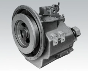
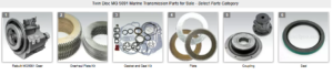
Parts Catalog for Twin Disc MG5091 Marine Transmissions
Rebuilt Twin Disc MG5091 Marine Transmissions
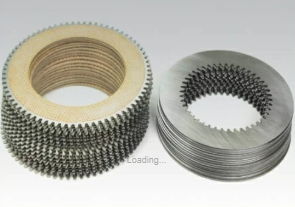
Plate Kit For Twin Disc MG5091 Marine Transmission
Gasket Kits For Twin Disc MG5091 Marine Transmission
Precision is everything when it comes to marine transmission assembly and adjustment. Whether you’re installing a new flange, torquing down a cover, or measuring shaft runout, accurate specs and tolerances are non-negotiable.
The Twin Disc MG-5091 Marine Gear is a precision-engineered hydraulic transmission, and its performance depends on parts being torqued, aligned, and shimmed within narrow limits. Failure to follow proper torque values and tolerances can result in:
- Oil leaks
- Shaft misalignment
- Gear wear
- Clutch slippage
- Catastrophic internal failure
This comprehensive 5,000-word guide covers everything technicians and rebuilders need to know about torque specifications and mechanical tolerances for the MG-5091. Whether you’re reassembling the housing or checking gear backlash, this post walks you through all the numbers — and the techniques — that matter most.
Refer to OEM service manual SM-259 for official values, calibration standards, and updates during overhaul procedures. This post is built to support mechanics and engineers using Diesel Pro Power’s aftermarket parts and rebuild kits.
Torque Settings for Twin Disc MG-5091 Marine Gear
Correct torqueing is one of the most crucial steps in transmission assembly. Improperly torqued fasteners can back out under vibration, distort flanges, or fail to hold seals — leading to gear misalignment, oil loss, or internal damage.
Below are the standard torque values (in foot-pounds and Newton-meters) for major components of the MG-5091. These figures are based on standard-grade fasteners and factory service procedure references Twin Disc marine transmission.
1. Flange Bolts
Flange bolts are responsible for securing the output coupling to the propeller shaft. These fasteners handle high torque loads under varying marine conditions and must be torqued evenly.
| Bolt Size | Grade | Torque (ft-lbs) | Torque (Nm) |
| 5/8″-18 | Grade 8 | 125–135 ft-lbs | 170–183 Nm |
| 3/4″-16 | Grade 8 | 180–200 ft-lbs | 244–271 Nm |
Best Practices:
- Always use a calibrated torque wrench.
- Apply Loctite 271 (red) or equivalent threadlocker.
- Torque in a star pattern to ensure even load distribution.
- Recheck torque after the first 10 hours of operation under load.
Pro Tip: Use anti-seize on stainless or saltwater-exposed fasteners to avoid galling.
2. Housing and Cover Bolts
These include bolts for:
- Top inspection covers
- Main case halves
- Oil pan (if applicable)
- Valve body covers
| Bolt Size | Torque (ft-lbs) | Torque (Nm) |
| 3/8″-16 | 30–35 ft-lbs | 40–47 Nm |
| 7/16″-14 | 50–55 ft-lbs | 68–75 Nm |
| 1/2″-13 | 75–85 ft-lbs | 102–115 Nm |
Tips:
- Use anaerobic flange sealant between case halves.
- Avoid overtightening small cover bolts — it can distort gasket surfaces.
- Always torque in a diagonal or cross pattern to prevent case warping.
3. Shaft Retaining Nuts
The input and output shaft nuts hold the entire rotating assembly together. Under-torquing or failing to stake these properly can cause total failure.
| Shaft | Thread Size | Torque (ft-lbs) | Torque (Nm) |
| Input Shaft | 1-1/4″-12 | 180–200 ft-lbs | 244–271 Nm |
| Output Shaft | 1-1/2″-12 | 225–250 ft-lbs | 305–339 Nm |
Best Practices:
- Use a shaft-holding tool to prevent internal damage.
- Apply non-permanent threadlocker (Loctite Blue).
- Stake nut into groove (if applicable).
- Torque before installing seals to avoid distortion.
4. Pump and Valve Assembly
Pump bolts and hydraulic valve fasteners must hold under high oil pressure and thermal expansion.
Component |
Torque (in-lbs) |
Torque (Nm) |
| Oil Pump Cover | 75–95 in-lbs | 8.5–10.7 Nm |
| Valve Body Bolts | 60–80 in-lbs | 6.7–9.0 Nm |
| Pressure Relief Plug | 20–25 ft-lbs | 27–34 Nm |
Always check for thread damage before reassembly and replace fasteners if corrosion is visible.
Tolerances for Twin Disc MG-5091 Marine Gear
Mechanical tolerances define the acceptable limits for component fitment, movement, and spacing. Staying within these tolerances is essential for clutch performance, gear alignment, oil sealing, and vibration reduction.
1. Shaft Runout
Runout is the amount of wobble in a rotating shaft. Excessive runout can cause vibration, uneven clutch wear, and seal damage.
Acceptable Shaft Runout:
| Shaft | Max Runout (TIR) |
| Input Shaft | 0.002″–0.004″ (0.05–0.10 mm) |
| Output Shaft | 0.003″–0.005″ (0.08–0.13 mm) |
Measuring Procedure:
- Mount shaft in housing.
- Position dial indicator on shaft journal.
- Rotate shaft 360° and record total indicated runout.
- If runout exceeds spec:
- Inspect shaft for bending
- Check bearing seating and preload
Note: Even minor runout can lead to excessive seal wear over time.
2. Gear Backlash
Backlash is the small amount of clearance between mating gear teeth. Too much = slop and noise. Too little = binding and heat.
Recommended Backlash:
| Gear Set | Acceptable Range |
| Input to Planetary | 0.004″–0.008″ (0.10–0.20 mm) |
| Planetary to Output | 0.006″–0.010″ (0.15–0.25 mm) |
How to Measure:
- Hold one gear stationary.
- Mount dial indicator on mating gear tooth.
- Rotate back and forth and record TIR.
- Adjust using shims or bearing preload if necessary.
Always measure backlash at ambient temperature, not after heat expansion.
3. Shaft Endplay
Endplay is the axial movement of a shaft within its housing. Too much endplay = hammering. Too little = heat and binding.
Endplay Specifications:
| Shaft | Endplay Range |
| Input Shaft | 0.003″–0.006″ (0.08–0.15 mm) |
| Output Shaft | 0.004″–0.008″ (0.10–0.20 mm) |
To Measure:
- Mount dial indicator at shaft end.
- Push/pull shaft to extremes.
- Record total movement.
Adjusting Endplay:
- Use shims under bearing races or thrust washers.
- Do not preload tapered bearings unless specified.
4. Clutch Pack Clearance
Clutch pack clearance affects engagement timing, pressure, and torque delivery.
Recommended Clearance:
| Clutch Stack | Total Clearance |
| Forward Clutch | 0.015″–0.030″ (0.38–0.76 mm) |
| Reverse Clutch | 0.015″–0.030″ (0.38–0.76 mm) |
Measurement Tip:
- Use feeler gauges between piston and first steel plate.
- Excess clearance = delayed engagement
- Tight clearance = dragging or failure to disengage
5. Seal Bore and Shaft Fitment
Improper seal-to-shaft clearance leads to oil leaks and premature seal failure.
Fit Specifications:
| Location | Fit Type | Tolerance |
| Shaft OD to Seal ID | Interference Fit | 0.001″–0.003″ |
| Seal OD to Bore ID | Press Fit | 0.002″–0.005″ |
Always measure with micrometer and verify seal seating with install tool.
Calibration and Measurement Tools
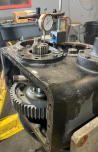
Technician uses a starrett dial indicator to measure the backlash between the gears on a Detroit Diesel engine.
To accurately measure the above tolerances, you’ll need:
- Dial indicator with mag base (for runout, backlash, endplay)
- Feeler gauges (for clutch clearance)
- Micrometer or calipers (for shaft/seal fits)
- Torque wrench (click-type or digital)
- Bore gauge (optional for housing checks)
- Thread pitch gauge and bolt ID chart
Summary
Technical Torque Specs and Tolerances for Twin Disc MG-5091 Marine Gear
Rebuilding the Twin Disc MG-5091 Marine Gear is a precise, high-stakes task. From flange bolt torque to clutch stack clearance, every number matters — because the performance and longevity of your transmission depend on precision.
Key Specs Overview:
Torque Specs:
- ✅ Flange Bolts: 125–135 ft-lbs
- ✅ Cover Bolts: 30–85 ft-lbs depending on size
- ✅ Shaft Nuts: 180–250 ft-lbs
- ✅ Valve Bolts: 60–95 in-lbs
Tolerances:
- ✅ Shaft Runout: Max 0.004″
- ✅ Gear Backlash: 0.004″–0.010″
- ✅ Endplay: 0.003″–0.008″
- ✅ Clutch Clearance: 0.015″–0.030″
Following these specs protects your investment, ensures clutch longevity, and keeps your vessel running smoothly in the harshest marine conditions.
Rebuilt Twin Disc MG5091 Marine Transmissions
Plate Kit For Twin Disc MG5091 Marine Transmission
Gasket Kits For Twin Disc MG5091 Marine Transmission
Videos About Twin Disc Transmissions
6 Reasons Your Twin Disc Transmission Has Low Oil Pressure
7 Reasons Your Twin Disc Transmission Is Overheating
3 Reasons Your Clutch Plates in Your Twin Disc Transmission Are Making Excessive Noise
Bull Gear On A Twin Disc Transmission
Rebuilt Twin Disc Transmissions