Torque Specs & Wear Limits For Detroit Diesel 671 Inline Engines (271, 371, 471, 671)

Explanation of Torque Specifications for Bolts, Nuts, and Studs to Ensure Proper Assembly
Torque specifications are vital for the correct assembly of the Detroit Diesel Series 71 engine. These specifications ensure that bolts, nuts, and studs are tightened to the precise levels necessary to maintain the structural integrity of the engine, while avoiding issues like over-tightening or under-tightening that could lead to component damage or failure.
Why Torque Specifications Matter
- Proper Clamping Force: Torque specifications ensure that engine components like the cylinder head, connecting rods, and crankshaft are securely fastened, maintaining the correct clamping force. This prevents leakage of fluids, such as oil or coolant, and ensures that parts don’t loosen during operation.
- Avoid Over-Tightening: Over-tightening can damage threads, cause bolts to snap, or warp components like the cylinder head. This may lead to improper sealing, leaks, or even catastrophic engine failure.
- Avoid Under-Tightening: Under-tightened bolts can loosen over time due to engine vibrations, potentially leading to misalignment, leaks, or the failure of critical engine parts.
Using the Right Tools
A calibrated torque wrench is essential to accurately applying the specified torque. Different components have different torque requirements, and in most cases, it is necessary to tighten bolts in multiple stages to ensure even distribution of force, particularly for parts under high stress like the cylinder head and crankshaft.
Exact Torque Specifications for Detroit Diesel Series 71 Inline Engine Components
-
Detroit Diesel 2-71 Torque Specifications
Thread Size (in.)DescriptionTorque Specifications lb-ft N-m 1/4-20 Standard Torque Specification 7-9 9-12 1/4-28Standard Torque Specification 8-10 11-14 Screw-Injector Rack Control Lever 2-3 3-4 5/16-18 Standard Torque Specification 13-17 18-23 5/16-24Standard Torque Specification 15-19 20-26 Nut-Lock-Push Rod 15-19 20-26 3/8-16Standard Torque Specification 30-35 41-47 Bolt-Air Inlet Housing to Blower 30-35 41-47 Bolt-Air Box Cover 10-12 14-16 Bolt-Oil Pan 10-12 14-16 Bolt-Injector Clamp 20-25 27-34 3/8-24Standard Torque Specification 35-39 47-53 Nut-Fuel Jumper Line 12-16 16-22 Nut-Exhaust Outlet Manifold Flange (Brass) 20-25 27-34 Nut-Injector Clamp 20-25 27-34 7/16-14Standard Torque Specification 46-50 62-68 Bolt-Blower to Block 55-60 75-81 7/16-20Standard Torque Specification 57-61 77-83 Bolt-Oil Strainer Shell to Adaptor 30-35 41-47 Bolt-Connecting Rod to Pin 55-60 75-81 Nut-Connecting Rod 60-75 81-102 Nut-Connecting Rod 60-75 81-95 1/2-13Standard Torque Specification 71-75 96-102 Bolt-Rocker Shaft Bracket to Cyl Head 90-100 122-136 1/2-20 Standard Torque Specification 83-93 113-126 9/16-12 Standard Torque Specification 90-100 122-136 9/16-18Standard Torque Specification 107-117 145-159 Bolt-Flywheel 180-190 244-258 5/8-11Standard Torque Specification 137-147 186-199 Bolt-Main Bearing (Boring) 165-175 224-237 Bolt-Main Bearing (Assembly) 180-190 244-258 Bolt-Cylinder Head 190-200 258-271 5/8-18Standard Torque Specification 168-178 228-241 Nut-Special Self Locking Nut (10SI Alternator) 40-60 54-81 Bolt-Lube Oil Filter Center 50-60 68-81 Nut-Alternator Pulley 70-80 95-108 3/4-18 Nut-Standard, Dipstick Tube 30-35 41-47 3/4-16 Standard Torque Specification 290-300 393-407 7/8-14 Standard Torque Specification 475-485 644-658 1-14 Bolt-Crankshaft End (1) 290-310 393-420 1-14 Bolt-Crankshaft End-1-1/2 Hex Head (2) 440-460 597-624 1-20 Nut-Cam and Balance Shaft 250-275 339-373 Detroit Diesel 2-71 Pipe Plug Torque Specifications
Plug Size (in.)DescriptionTorque Specifications lb-ft N-m 1/8-27 Plug-Pipe (3/4 Taper) 10-12 14-16 1/4-18 Plug-Pipe (3/4 Taper) 14-16 19-22 1/4-18 Plug-Pipe (7/8 Taper) 14-16 19-22 3/8-18 Plug-Pipe (3/4 Taper) 18-22 24-30 3/8-18 Plug-Pipe (7/8 Taper) 18-22 24-30 1/2-14 Plug-Pipe (3/4 Taper) 23-27 31-37 1/2-14 Plug-Pipe (7/8 Taper) 23-27 31-37 3/4-14 Plug-Pipe (3/4 Taper) 33-37 45-50 3/4-14 Plug-Pipe (7/8 Taper) 33-37 45-50 1-11 1/2 Plug-Pipe (3/4 Taper) 75-85 102-115 1-11 1/2 Plug-Pipe (7/8 Taper) 75-85 102-115 1 1/4-11 1/2 Plug-Pipe (3/4 Taper) 95-105 129-142 1 1/2-11 1/2 Plug-Pipe (3/4 Taper) 110-130 149-176 1 1/2-11 1/2 Plug-Pipe (7/8 Taper) 110-130 149-176 1/2-20 Plug-Fuel Pump Relief Valve 18-22 24-30 Detroit Diesel 2-71 Stud Torque Specifications
Thread Size (in.)DescriptionTorque Specifications lb-ft N-m 7/16-20 Stud Standard 30-35 41-47
Torque Specifications For Detroit Diesel Series 71 (Inline Except 2 Cylinder)
Thread Size (in.)DescriptionTorque Specifications lb-ft N-m 1/4-20Standard Torque Specification 7-9 9-12 Bolt-Injector Control Shaft Bracket 10-12 14-16 Bolt-Cam Follower Guide 12-16 16-22 1/4-28Standard Torque Specification 96-120 130-163 Screw-Inj. Rack Control Lever 24-36 33-49 5/16-18Standard Torque Specification 156-204 212-277 Bolt-Oil Pan (Cast) – Hard Gasket 13-21 18-28 Bolt-Oil Pan (Low Pan or In Aluminum F/W Hsg. & Front Cover) 10-12 14-16 5/16-24Standard Torque Specification 15-19 20-26 Nut-Lock-Push Rod 15-19 20-26 Bolt-Blower Drive Coupling Rotor Gear 20-25 27-34 Bolt-Blower Rotor Gear Hub 25-30 34-41 Nut-Lock Valve Bridge Adj. Screw 20-25 27-34 7/16-14Standard Torque Specification 46-50 62-68 Bolt-Tach. Drive 30-35 41-47 Bolt-Lifter Bracket 55-60 75-81 Bolt-Valve Bridge Guide (Nylon-Insert) 46-50 62-68 Bolt-Flywheel Housing Large Hole Cover 30-35 41-47 Bolt-Blower to Block 55-60 75-81 7/16-20Standard Torque Specification 57-61 77-83 Connector-Fuel (Steel Washer) 40-45 54-61 Nut-Exhaust Manifold 30-35 41-47 Nut-Connecting Rod 60-70 81-95 Connector- Fuel (Nylon Insert) 30-35 41-47 Nut-Connecting Rod 60-70 81-95 Bolt-Connecting Rod to Pin 55-60 75-81 3/8-16Standard Torque Specification 30-35 41-47 Bolt-Camshaft & Seal End Bearing 35-40 47-54 Bolt-Flywheel Hsg to Idler Gear & Dummy 40-45 54-61 Bolt-Air Box Cover 10-15 14-20 Bolt-Rocker Cover Hold-Down Special 12-Point 15-20 20-27 Bolt-Injector Clamp 20-25 27-34 Bolt-Oil Pan 10-20 14-27 3/8-24Standard Torque Specification 35-39 47-53 Bolt-Accessory Drive to Balance Gear (Steel Disc) 45-50 61-68 Bolt-Lower Front Cover 25-30 34-41 Nut-Water Manifold 20-25 27-34 Bolt-Balance Weight to Hub 25-30 34-41 Bolt-Balance Weight to Timing Gear 25-30 34-41 Bolt & Nut-Blower Drive Gear 25-30 34-41 Nut-Exhaust Outlet Manifold Flange 20-25 27-34 Nut-Fuel Jumper Line O Ring 13-17 18-23 Nut-Fuel Jumper Line Flared 11-13 15-18 Nut-Injector Clamp 20-25 27-34 1/2-13Standard Torque Specification 71-75 96-102 Bolt-Flywheel Housing 90-100 122-136 Bolt-Idler Gear Hub and Dummy Hub 80-90 108-122 Bolt-Tach. Drive Cover 30-35 41-47 Bolt-Engine Mtg Brkt to Frt Cover 90-100 122-136 Bolt-Front Cover (Crankshaft) 80-90 108-122 Bolt-Flywheel Housing Large Hole Cover 30-35 41-47 Bolt-Rocker Shaft Bracket to Cyl Head 90-100 122-136 1/2-20Standard Torque Specification 83-93 113-126 Bolt-Blower Rotor Gear Retainer 55-65 75-88 Nut-Oil Pump Drive Idler Gear Shaft 60-70 81-95 9/16-12 Standard Torque Specification 90-100 122-136 9/16-18Standard Torque Specification 107-117 145-159 Nut-Crankshaft Bearing Cap 140-150 190-203 Bolt-Flywheel 180-190 244-258 Bolt-Flywheel (V-53) 12-16 16-22 Bolt-Cylinder Head 140-150 190-203 5/8-11Standard Torque Specification 137-147 186-199 Bolt-Starter to Aluminum Flywheel Housing 95-105 129-142 Bolt-Main Bearing (Boring) 165-175 224-237 Bolt-Main Bearing (Assembly) 180-190 244-258 Bolt-Cylinder Head 190-200 258-271 5/8-18Standard Torque Specification 168-178 228-241 Bolt-Lube Oil Filter Center 50-60 68-81 Nut-Alternator Pulley 70-80 95-108 Nut-Special Self Locking Nut (10SI Alternator) 40-60 54-81 Bolt-Main Bearing (Boring) 140-155 190-210 Bolt-Main Bearing (Assembly) 155-185 210-251 Nut-Cylinder Head 190-200 258-271 3/4-10 Bolt-Crankshaft Main Bearing 280-290 380-393 3/4-16Standard Torque Specification 290-300 393-407 Nut-Accessory Drive Pulley 120-140 163-190 3/4-18 Nut Standard, Dipstick Tube 30-35 41-47 3/4-24 Bolt-Balance Weight Cover 25-30 34-41 7/8-14 Standard Torque Specification 475-485 644-658 7/8-18 Bolt-Oil Pump Relief Valve Cover 25-35 34-47 1-14 Bolt Crankshaft End 440-460 597-624 1 1/8-18 Nut-Cam and Balance Shaft 300-325 407-441 1 3/4-16 Nut-Transfer Drive Gear (Marsden) 375-400 508-542 Torque Specs For Detroit Diesel Series 71 (Inline Except 2 Cylinder) Pipe Plug
Plug Size in.DescriptionTorque Specifications lb-ft N-m 1/8-27 Plug-Pipe (3/4 Taper) 10-12 14-16 1/4-18 Plug-Pipe (3/4 Taper) 14-16 19-22 1/4-18 Plug-Pipe (3/4 Taper) 38-42 52-57 1/4-18 Plug-Pipe (7/8 Taper) 14-16 19-22 3/8-18 Plug-Pipe (3/4 Taper) 18-22 24-30 3/8-18 Plug-Pipe (7/8 Taper) 18-22 24-30 1/2-14 Plug-Pipe (3/4 Taper) 23-27 31-37 1/2-14 Plug-Pipe (7/8 Taper) 23-27 31-37 3/4-14 Plug-Pipe (3/4 Taper) 33-37 45-50 3/4-14 Plug-Pipe (7/8 Taper) 33-37 45-50 1-11 1/2 Plug-Pipe (3/4 Taper) 75-85 102-115 1-11 1/2 Plug-Pipe (7/8 Taper) 75-85 102-115 1 1/4-11 1/2 Plug-Pipe (3/4 Taper) 95-105 129-142 1 1/4-11 1/2 Plug-Pipe (7/8 Taper) 95-105 129-142 1 1/2-11 1/2 Plug-Pipe (3/4 Taper) 110-130 149-176 1 1/2-11 1/2 Plug-Pipe (7/8 Taper) 110-130 149-176 1/2-20 Plug-Fuel Pump Relief Valve 18-22 24-30 1 1/4-16 Plug-Oil Filter Bypass valve 95-105 129-142 Torque Specs For Detroit Diesel Series 71 (Inline Except 2 Cylinder) Stud
Thread Size (in.)DescriptionTorque Specifications lb-ft N-m 7/16-20 Stud Standard 30-35 41-47
Parts Catalog for 371 Detroit Diesel Marine Engine
Parts Catalog for 471 Detroit Diesel Marine Engine
Parts Catalog for 671 Detroit Diesel Marine Engine
Wear Limits for Critical Engine Parts and How to Measure These During Inspections (Covering Detroit Diesel 271, 371, 471, 671 Engines)
Wear limits define the acceptable range of wear for engine components. Exceeding these limits can compromise the performance and reliability of the engine. Regular inspections and measurements of critical parts are essential to identify excessive wear before it leads to engine failure.
Measuring Critical Engine Parts for Wear
- Cylinder Bores:

Detroit Diesel 671 Cylinder Block
- Wear Limit: Maximum bore diameter should not exceed 0.010 inches (0.25 mm) over the original bore size.
- How to Measure: Use a dial bore gauge to measure the diameter at the top, middle, and bottom of the cylinder at multiple angles. If the bore is excessively worn or out of round, it should be re-bored and fitted with oversized pistons.
- Pistons and Rings:

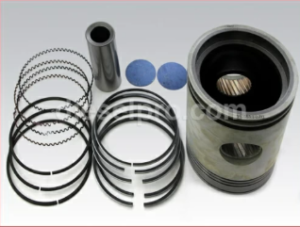
Trunk type piston for Detroit Diesel 671 Engine
- Piston Diameter Wear Limit: Piston skirts should not show more than 0.003 inches (0.08 mm) of wear from the original diameter.
- Ring End Gap Wear Limit: The gap between piston ring ends when inserted into the cylinder should not exceed 0.045 inches (1.14 mm) for top rings and 0.055 inches (1.40 mm) for second rings.
- How to Measure:
- Use a micrometer to measure the piston skirt diameter at multiple points around the skirt.
- For piston rings, place the ring inside the cylinder and measure the gap using a feeler gauge. If the end gap exceeds the wear limit, the rings need to be replaced.
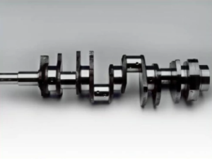
Crankshaft Journals:

Main Bearing Journal Wear Limit: Should not exceed a diameter reduction of 0.002 inches (0.05 mm).
-
- Rod Bearing Journal Wear Limit: The rod bearing journal should not exceed a reduction of 0.003 inches (0.08 mm) in diameter.
- How to Measure: Use a micrometer to measure the journal diameters and compare them with the manufacturer’s original specifications. If wear exceeds these limits, the crankshaft may need to be re-ground and oversized bearings installed.
- Bearing Clearances:
-
Main Bearing Clearance: Should be between 0.0015 to 0.003 inches (0.038 to 0.076 mm).
- Rod Bearing Clearance: Should be between 0.001 to 0.003 inches (0.025 to 0.076 mm).
- How to Measure: Use plastigage to measure bearing clearances during assembly. If the clearances are outside of specifications, replace the bearings.
-
- Valve and Valve Seats:
-
Valve Stem Wear Limit: The valve stem diameter should not exceed 0.002 inches (0.05 mm) of wear.
- Valve Seat Width Wear Limit: The valve seat width should not exceed 0.015 inches (0.38 mm).
- How to Measure: Use a micrometer to measure the valve stem diameter. For valve seat wear, check for pitting or uneven wear using a valve seat gauge. Re-grind or replace valve seats if necessary.
-
- Camshaft Lobes and Lifters:
- Camshaft Lobe Wear Limit: Maximum wear should not exceed 0.002 inches (0.05 mm) on cam lobes.
- Lifter Wear Limit: Lifters should not exceed 0.0015 inches (0.038 mm) of wear.
- How to Measure: Use a micrometer to measure camshaft lobe height and inspect lifters for wear. Replace if wear exceeds limits.
Importance of Adhering to These Specifications to Prevent Engine Failures and Maintain Reliability

Strict adherence to torque specifications and wear limits is crucial to maintaining engine performance and reliability. Improper torque can lead to part misalignment, leaks, or even catastrophic engine failure, while ignoring wear limits can result in decreased efficiency, increased fuel consumption, and potential damage to other engine components.
- Torque Adherence: By applying the correct torque to bolts, nuts, and studs, technicians ensure that components are properly secured and evenly clamped, avoiding damage from over- or under-tightening.
- Monitoring Wear Limits: Regular inspection and replacement of parts that exceed wear limits prolong engine life and prevent unexpected failures. Early detection of wear and proper adjustments or part replacements are key to maximizing engine efficiency and reliability.
By following the recommended torque specifications and monitoring wear limits during routine maintenance, you can ensure that the Detroit Diesel Series 71 engine operates efficiently and remains reliable throughout its service life.


 Free US Calls: 1-888-433-4735
 International: 305-545-5588