

 Free US Calls: 1-888-433-4735
 International: 305-545-5588
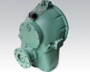
Allison M Rebuilt Marine Transmission
Overhaul Kit & Related Components For Allison M
Allison M Seals
Allison M Clutch Plates
Allison M Hydraulic Pump
Allison M Selector Valve & Related Components
Allison M Bearings & Related Components
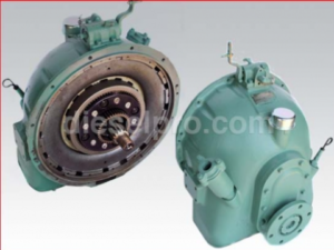
Allison MH Rebuilt Transmission
Allison MH Overhaul Kit & Related Components
Allison MH Seals
Allison MH Clutch Plates & Related Components
Allison MH Hydraulic Pump
Allison MH Selector Valve
Allison MH Bearings & Related Components
Disconnecting Cooling and Control Systems
Before removing the transmission from the vessel, disconnecting all auxiliary systems is essential to prevent component damage and ensure personnel safety. Begin by shutting off the engine and allowing the transmission to cool to ambient temperature. Make sure all pressure has dissipated within the hydraulic circuits, and the transmission is safe to service.
Step-by-Step Cooling System Disconnection
-
Drain Oil Cooler and Hoses
Begin by removing the transmission oil cooler lines from the transmission housing. Place drip pans beneath the fittings to capture residual oil. Use two adjustable wrenches—one to hold the fitting and one to turn the nut—to prevent twisting or cracking the cooler fittings. Label the hoses and ports for accurate reassembly. Cap both ends to prevent contamination from entering the system.
-
Disconnect Temperature and Pressure Sensors
If the transmission is outfitted with temperature or pressure monitoring sensors connected to the control panel, unplug these electrical connections carefully. Secure the harnesses away from sharp edges or any movement area during removal.
-
Remove Control Linkages and Shift Cables
Shift cables must be disconnected from the manual selector valve assembly. Before disconnection, mark the exact location of the shift linkage using scribe marks or colored tape to assist in realignment during reinstallation. Use the proper wrenches to loosen cable clamps or brackets and inspect for wear or corrosion. Clean all hardware thoroughly and bag them with labels to simplify the reinstall process.
-
Remove Breather and Fill Tube Cap
Remove the breather and oil fill cap to relieve any residual pressure and allow for ventilation during transmission extraction.
Supporting the Weight Safely
Allison M & MH marine transmissions are compact but relatively heavy, and their removal requires appropriate lifting techniques and secure handling to avoid personal injury and equipment damage.
Required Tools and Equipment
- 1/4-ton minimum capacity hoist with chain sling
- Lifting eye bolts or special adapter plates
- Transmission cradle or support bench
- Wood blocks or rubber pads for cushioning
Lifting Techniques and Safety Tips
- Identify Proper Lift Points
Use the bearing retainer bolts or designated lifting lugs as shown in the service documentation. Do not lift by cooling lines, cables, or oil pans. Thread lifting bolts into the transmission housing using the appropriate size and thread pitch.
- Attach Sling Evenly
Connect a three-point or four-point chain sling to the lifting points. Ensure even load distribution and maintain horizontal balance. Avoid tilting the transmission which could cause fluid spillage or housing strain.
- Stabilize the Load
Prior to hoisting, verify all rigging is secure. Lift the transmission slightly to test stability and make minor adjustments if needed. Use a spotter during lifting and moving to monitor for swing or shift.
- Lower Onto Workbench or Cart
Gently lower the transmission onto a padded surface to prevent denting or cracking the housing. Do not rest it on sharp or uneven surfaces.
Removing Fasteners and Couplings
Now that auxiliary systems are detached and the unit is supported, it’s time to separate the transmission from the engine and shaft couplings.
Engine to Transmission Fasteners
- Mark Flange Orientation
Use a paint pen or punch to mark the relative orientation of the transmission to the engine bell housing. This helps maintain balance and alignment during reinstallation.
- Remove Mounting Bolts
Use a breaker bar and socket to remove the bolts connecting the transmission housing to the engine flywheel housing. Depending on the model, there are typically 6–8 bolts. Remove them in a crisscross pattern to avoid stress points.
- Loosen Pilot Shaft
Some Allison M/MH transmissions use a splined input shaft that mates with the engine flywheel. Slowly work the transmission away from the flywheel housing while maintaining horizontal alignment to avoid damaging splines or seals.
Shaft Coupling and Propeller Shaft Detachment
-
Block the Propeller Shaft
Ensure the propeller shaft is properly secured and blocked to prevent movement during disassembly.
-
Remove Output Flange Bolts
Disconnect the transmission flange from the shaft coupling. Use a hammer and brass drift to tap it loose if corroded. If a flexible coupling or damper plate is present, inspect and remove it accordingly.
-
Check for Wear
Before removing the shaft coupling completely, inspect it for worn keyways, fretting, or rust. Tag any hardware for reuse or replacement.
Extracting from Engine Room
Removing the transmission from its installed position requires navigating confined spaces in most marine engine rooms.
Planning the Extraction Route
- Map the Route
Plan a clear path from the engine bay to the extraction point. Remove obstructions such as hatches, engine covers, or seating. Enlist additional help if needed.
- Lay Down Protective Materials
Use rubber mats or plywood to protect flooring and structural areas. Avoid placing heavy tools or parts directly on fiberglass or aluminum decks.
- Guide the Transmission Out
With a helper guiding the transmission from below, lift it slowly using the overhead hoist or gantry. Keep the unit level to prevent oil sloshing and maintain alignment with the support sling.
- Set Down on Safe Surface
Once removed, place the transmission in a safe, stable location. Strap it down if being transported offsite for overhaul.
Reinstallation Alignment Tips
After inspection or overhaul, reinstalling the transmission is just as critical as removal. Follow these steps for precision and safety.
Preparation Before Reinstallation
- Clean all mating surfaces using lint-free rags and degreaser.
- Inspect dowel pins and pilot shaft for wear or scoring.
- Replace any gaskets or O-rings with fresh components.
Aligning Input Shaft and Bell Housing
- Apply Assembly Grease
Lightly coat the input shaft splines with high-pressure assembly lubricant to aid insertion and prevent galling.
- Align Dowel Pins First
Using the marks made during removal, align the transmission housing with the bell housing and guide it in evenly.
- Avoid Forcing the Mating
Do not use bolts to draw the transmission into position. If it does not seat smoothly, withdraw and realign. Forcing it may damage the input shaft or clutch assembly.
- Torque Bolts to Spec
Once seated, torque the engine-to-transmission bolts in a star pattern to the specified value. Refer to the torque chart in the service manual for your specific model.
Coupling the Output Shaft
- Align Flanges
Reconnect the output flange to the propeller shaft. Ensure keys or splines are correctly aligned and tapped into position.
- Torque Flange Bolts
Use a torque wrench and tighten in stages. Apply thread locker if required.
- Reinstall Shift Linkages and Sensors
Connect shift cables, sensors, and breathers exactly as labeled during disassembly. Recheck adjustments to ensure full gear engagement.
Final Pre-Start Checklist
Before running the engine with the newly installed transmission, perform this checklist to verify all systems are safe and ready.
- Transmission filled with proper oil to correct level
- Cooler lines connected and clamped securely
- Electrical connectors reattached and secured
- Shift linkage adjusted and tested for full range of motion
- Breather installed and unobstructed
- Output flange and shaft secured and torqued
- No tools or debris left in engine compartment
- Transmission mounted securely and aligned
Once verified, proceed with the Initial Startup Procedure For Allison M & MH Marine Transmissions.
Summary
Removing and reinstalling an Allison M or MH marine transmission is a comprehensive task that requires precision, proper planning, and attention to safety protocols. Missteps during disassembly can cause damage to internal components or the vessel’s drivetrain. Similarly, poor alignment during reinstallation can result in vibration, noise, or even catastrophic failure.
Whether you’re servicing the unit in a shipyard, marina, or onboard, always follow best practices for lifting, handling, alignment, and sealing. Use quality aftermarket parts where replacements are necessary—especially from trusted marine suppliers like Diesel Pro Power.
Allison M Rebuilt Marine Transmission
Overhaul Kit & Related Components For Allison M
Allison M Seals
Allison M Clutch Plates
Allison M Hydraulic Pump
Allison M Selector Valve & Related Components
Allison M Bearings & Related Components
Allison MH Rebuilt Transmission
Allison MH Overhaul Kit & Related Components
Allison MH Seals
Allison MH Clutch Plates & Related Components
Allison MH Hydraulic Pump
Allison MH Selector Valve
Allison MH Bearings & Related Components