

 Free US Calls: 1-888-433-4735
 International: 305-545-5588

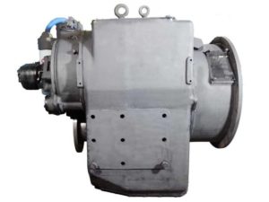
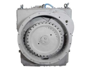
Proper diagnosis and timely resolution of transmission faults in the Twin Disc MG-540 marine gear are critical for safe operation and long-term reliability. This expanded troubleshooting guide focuses on identifying issues related to electronic controls, hydraulic function, mechanical engagement, and oil cooling systems. Each category includes diagnostic methods, correction steps, and reference specifications derived from real-world use and OEM data.
EC050 Control Diagnostics
Understanding LED Codes: Green, Red, Flashing
The EC050 electronic control module features a three-LED system that serves as a real-time diagnostic interface for operators and technicians. Each LED indicates system status, faults, or operating modes.
| Power LED | Solenoid A | Solenoid B | Condition |
| Green | Green | Off | Forward (Cruise) |
| Green | Red | Off | Forward (Troll) |
| Green | Off | Green | Reverse (Cruise) |
| Green | Off | Red | Reverse (Troll) |
| Green | Off | Off | Neutral |
| Red | Off | Off | Low voltage (<9.0V) |
| Flashing Green/Yellow | — | — | Direction input active at startup |
| Flashing Red | — | — | Coil fault (open/short) |
| Red (Both Solenoids) | — | — | Program data error (replace module) |
Troubleshooting Cruise, Troll, and Neutral Faults
Common issues with EC050-controlled MG-540 units can often be traced to power input, switch logic, or sensor signal errors.
Cruise Mode Does Not Engage
- Ensure troll switch is open (not active).
- Verify engine and transmission RPM signals are reaching the EC050.
- Re-enter Cruise mode and maintain for 20+ seconds to allow gear ratio learning.
- If Solenoid LEDs do not illuminate, check for output voltage to solenoids and reprogram module if required.
Troll Mode Failure
- Ensure Troll switch is closed and functional.
- Inspect slip speed sensor wiring and confirm resistance between terminals C-B is ~4600 ohms.
- LED A or B flashing red = coil open or shorted. Check coil resistance (7–10 ohms).
- Alternating flashing red LEDs = missing engine speed signal; check engine sensor signal amplitude.
Neutral Faults
- Transmission stuck in gear?
- Both solenoid LEDs may be on — indicating dual direction command.
- Reset to neutral, cycle power, verify shift logic sequence.
Valve-Specific Troubleshooting
Issues With GP, Mechanical, or Electric Valves
MG-540 units may be equipped with:
- GP Valve (1020941B) with EC050
- Mechanical Valve (XB2015A)
- Electric Valve (1020317 Series)
Mechanical Valve
- Engages via manual linkage; ensure proper cable adjustment.
- Clutches may fail to engage if selector lever does not fully reach detent.
Electric Valve
- 12V/24V power required; check toggle switch wiring and solenoid terminals.
- Solenoid resistance should be within 7–10 ohms.
GP Valve + EC050
- Controlled entirely via solenoid modulation and logic inputs.
- Use LED diagnostics to identify errors; inspect oil passage cleanliness for inconsistent actuation.
Solenoid Diagnostics and Resistance Checks
Use a digital multimeter to verify solenoid and speed sensor circuit integrity.
| Component | Terminals | Expected Resistance |
| Solenoid A | Ground – A | 7–10 ohms |
| Solenoid B | Ground – B | 7–10 ohms |
| Prop Speed Sensor | C – B | ~4600 ohms |
| Engine Speed Sensor | — | ~913 ohms |
Check all solenoid connectors for:
- Pin corrosion
- Loose fit
- Paint or oil contamination
- Broken internal wires
Voltage drop during operation should remain below 1V.
Hydraulic and Mechanical Faults
Low Pressure, Fluid Contamination, Erratic Shifting
Symptoms such as hard engagement, clutch slip, or lube oil alarms point toward hydraulic issues.
| Symptom | Common Causes |
| Low Lube Pressure | Plugged suction strainer, pump air leak, failing pump |
| Low Main Pressure | Faulty regulator valve, defective proportional valve, clogged filters |
| Clutch Slipping | Worn clutch plates, low apply pressure, damaged proportional valve |
| Harsh Engagement | Faulty regulator profile module, incorrect shimming, high oil viscosity |
| Erratic Shift Response | EC050 fault, dual direction input, stuck manual override pin |
Corrective Actions:
- Clean or replace suction strainers and filters.
- Use the Digital Pressure Transducer Kit (BOM 42168) to test pressures at forward, reverse, and neutral ports.
- Measure clutch apply pressure with engine at idle and in gear:
- Normal range: 226–265 psi
- Normal range: 226–265 psi
- Main regulator adjustment or replacement may be necessary if out of spec.
Testing With Digital Pressure Transducer Kit (BOM 42168)
This kit includes:
- Two pressure sensors (0–500 psi)
- Quick-connect hydraulic fittings
- Power supply box
- Output terminals to multimeter
Test Procedure:
- Connect sensors to forward and reverse pressure ports.
- Crank engine; verify rise in pressure as gear is selected.
- Record pressures at idle and full engine RPM.
- Compare to published specs by gear ratio and shift position.
This data helps isolate faults to either the hydraulic or electronic control circuit.
Heat Exchanger Failure and Oil Line Leakage
Heat exchanger issues often appear as high oil temperatures, foaming, or even clutch failure.
Heat Exchanger Fault Indicators:
- Rapid oil temperature rise >200°F
- Oil pressure instability
- Breather cap blowout from overheating
Inspection Checklist:
- Check for zinc rod depletion (replace if 50% eroded).
- Flush exchanger with freshwater or cleaning solution.
- Inspect oil cooler lines for:
- Kinks
- Collapsed sections
- Clamp failures
Oil Line Leakage
Leaks may originate at:
- Oil pump housing flanges
- Heat exchanger inlet/outlet
- Hose crimps or fittings
- Valve bodies (especially GP valve on EC050 setups)
Resolution:
- Replace compromised hoses
- Reseal pipe threads with marine-grade thread sealant
- Re-torque fittings to spec: typically 25–35 lb-ft for 3/8” lines
Troubleshooting Chart Summary
| Problem | Probable Cause | Recommended Fix |
| Output rotates in Neutral | Warped clutch plates, valve leak | Overhaul clutch, replace proportional valve |
| Oil spurting from breather | Overfilled, wrong oil type | Drain to correct level; replace with TO-2 oil |
| Harsh gear engagement | Faulty profile module or sensor | Reprogram module, replace sensor |
| Noise during operation | Misalignment, damaged gear | Realign drivetrain, inspect and replace gear |
| Low Lube Pressure | Suction screen clogged | Clean or replace screen |
| Solenoid not responding | Open coil or poor wiring | Measure resistance; repair connector |
| EC050 error with no LED | Program corruption | Replace or reflash control module |
| Trolling unstable | Sensor signal loss | Repair or replace propeller speed sensor |
Final Notes
Troubleshooting the Twin Disc MG-540 requires a combined understanding of mechanical systems, hydraulic dynamics, and electronic diagnostics. Whether using LEDs for fault indication, pressure sensors for hydraulic validation, or detailed inspection of heat exchangers and valve assemblies, this guide provides a structured, proven approach.
Videos About Twin Disc Transmissions
6 Reasons Your Twin Disc Transmission Has Low Oil Pressure
7 Reasons Your Twin Disc Transmission Is Overheating
3 Reasons Your Clutch Plates in Your Twin Disc Transmission Are Making Excessive Noise
Bull Gear On A Twin Disc Transmission
Rebuilt Twin Disc Transmissions