

 Free US Calls: 1-888-433-4735
 International: 305-545-5588

Proper valve adjustment is one of the most critical maintenance tasks for ensuring efficient and reliable operation of Detroit Diesel 53 Series engines. Over time, valve clearances naturally shift due to engine wear, thermal expansion, and material settling, which can lead to reduced performance, increased fuel consumption, and potential engine damage. This guide will walk you through every step of the process, with detailed explanations, tips, and troubleshooting advice.
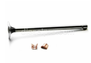
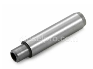
Valve & Related Components for Detroit Diesel 353 Non – Turbo Marine & Industrial Engines
Valve & Related Components for Detroit Diesel 353 Turbo Marine & Industrial Engines
Valve & Related Components for Detroit Diesel 453 Non – Turbo Marine & Industrial Engines
Valve & Related Components for Detroit Diesel 453 Turbo Marine & Industrial Engines
Valve & Related Components for Detroit Diesel 6V53 Non – Turbo Marine & Industrial Engines
Valve & Related Components for Detroit Diesel 6V53 Turbo Marine & Industrial Engines
Valve & Related Components for Detroit Diesel 8V53 Non – Turbo Marine & Industrial Engines
Valve & Related Components for Detroit Diesel 8V53 Turbo Marine & Industrial Engines
Why Valve Adjustments Are Important
Valve adjustments ensure the precise timing and operation of the intake and exhaust valves, which are critical to the engine’s combustion process. Here’s why regular valve adjustments are essential:
- Optimized Combustion: Proper valve clearance allows the valves to open and close at the right time, ensuring efficient air intake and exhaust gas expulsion.
- Improved Fuel Efficiency: Misadjusted valves can lead to incomplete combustion, resulting in wasted fuel and increased operating costs.
- Reduced Wear: Excessive valve lash (clearance) can cause hammering of the valve train components, while insufficient clearance can result in overheating and wear of the valve and seat.
- Enhanced Performance: Maintaining correct valve timing supports consistent power delivery and smooth engine operation.
- Prevention of Damage: Neglecting valve adjustments can lead to serious issues such as valve burnout, piston contact, or even catastrophic engine failure.
Tools and Preparation
Required Tools
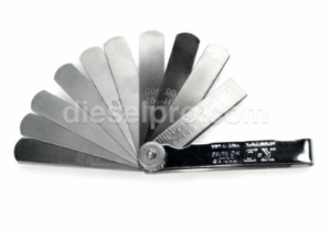
- Feeler Gauges: Used to measure valve clearance accurately. Ensure the set includes gauges as thin as 0.001″.
- Torque Wrench: For tightening bolts and locknuts to manufacturer-specified torque values.
- Basic Hand Tools: A combination of wrenches, screwdrivers, and sockets.
- Dial Indicator or Timing Pin: For accurate positioning of the crankshaft at Top Dead Center (TDC).
- Barring Tool: Helps rotate the crankshaft manually for precise positioning.
Safety Precautions
- Work on a Cool Engine: The engine should be at ambient temperature unless specified otherwise in the service manual. A hot engine can lead to inaccurate measurements due to thermal expansion.
- Disconnect the Battery: To prevent accidental engine starting during the procedure.
- Keep the Area Clean: Use lint-free cloths to wipe down components and prevent debris from entering the engine.
Preliminary Inspection
Before beginning the adjustment process, conduct a thorough visual inspection of the valve train components:
- Rocker Arms: Look for signs of scoring, cracks, or excessive wear at the pivot points.
- Push Rods: Roll them on a flat surface to check for bends and inspect the ends for wear.
- Valve Springs: Examine for fractures, rust, or loss of tension.
- Valve Bridges (on 4-valve heads): Ensure proper alignment and check for wear.
Step 1: Preparing for the Adjustment
Gaining Access to the Valves
- Remove the Valve Cover:
- Use the appropriate socket to remove the bolts securing the valve cover.
- Carefully lift the cover to avoid damaging the gasket. If the gasket shows signs of wear or cracking, replace it.
- Clean the Area:
- Wipe down the exposed components with a clean, lint-free cloth to remove oil, dirt, and debris.
- Wipe down the exposed components with a clean, lint-free cloth to remove oil, dirt, and debris.
Positioning the Crankshaft
- Locate TDC for Cylinder 1:
- Rotate the crankshaft using a barring tool until Cylinder 1 is at TDC on the compression stroke.
- Verify TDC using timing marks on the crankshaft pulley or a dial indicator.
- Follow the Engine’s Firing Order:
- Note the firing order of your specific Detroit Diesel 53 Series engine. For example, the 6V53 typically uses a firing order of 1-5-3-6-2-4.
- Plan the adjustment sequence accordingly.
Step 2: Measuring Valve Clearance
Accurate valve clearance measurement is the cornerstone of a successful adjustment. Follow these steps for precise results:
- Identify the Correct Valve Pair:
- At TDC, both the intake and exhaust valves for the corresponding cylinder will be in the closed position.
- At TDC, both the intake and exhaust valves for the corresponding cylinder will be in the closed position.
- Insert the Feeler Gauge:
- Slide the appropriate feeler gauge between the valve stem and the rocker arm pallet.
- Recommended clearances for Detroit Diesel 53 Series engines:
- Intake Valves: 0.013” (cold engine).
- Exhaust Valves: 0.026” (cold engine).
- Check the Fit:
- The feeler gauge should slide through with slight resistance. If the gauge is too tight or too loose, the clearance is incorrect.
- The feeler gauge should slide through with slight resistance. If the gauge is too tight or too loose, the clearance is incorrect.
- Record Measurements:
- Log the measured clearances for each valve. This documentation can help identify wear patterns over time.
- Log the measured clearances for each valve. This documentation can help identify wear patterns over time.
Step 3: Adjusting Valve Clearance
Loosening the Adjustment Screw
- Locate the Locknut:
- Each rocker arm adjustment screw is secured with a locknut. Loosen this nut using a wrench.
- Each rocker arm adjustment screw is secured with a locknut. Loosen this nut using a wrench.
- Turn the Adjustment Screw:
- Use a screwdriver to turn the adjustment screw:
- Clockwise to decrease clearance.
- Counterclockwise to increase clearance.
- Use a screwdriver to turn the adjustment screw:
Setting the Correct Clearance
- Recheck with Feeler Gauge:
- Insert the feeler gauge again while adjusting the screw. Stop turning when the gauge slides through with a slight drag.
- Insert the feeler gauge again while adjusting the screw. Stop turning when the gauge slides through with a slight drag.
- Tighten the Locknut:
- Hold the adjustment screw in place with a screwdriver while tightening the locknut with a wrench.
- Use a torque wrench to secure the locknut to the specified torque value (typically 50-55 lb-ft)
- Hold the adjustment screw in place with a screwdriver while tightening the locknut with a wrench.
- Verify the Adjustment:
- Slide the feeler gauge through one final time to confirm the clearance remains accurate.
- Slide the feeler gauge through one final time to confirm the clearance remains accurate.
Repeat for All Valves
- Rotate the Crankshaft:
- Move to the next cylinder in the firing order and repeat the process.
- Ensure the crankshaft is positioned at TDC for each respective cylinder.
Step 4: Post-Adjustment Verification
Check the Entire Valve Train
- Inspect Adjustments:
- Confirm that all intake and exhaust valves have been adjusted and locknuts are tightened to specification.
- Confirm that all intake and exhaust valves have been adjusted and locknuts are tightened to specification.
- Rotate the Crankshaft:
- Manually rotate the crankshaft through at least two complete revolutions to ensure smooth operation of the valve train.
- Manually rotate the crankshaft through at least two complete revolutions to ensure smooth operation of the valve train.
- Look for Interference:
- Pay close attention to any unusual resistance or noises during rotation, which may indicate improper adjustment.
- Pay close attention to any unusual resistance or noises during rotation, which may indicate improper adjustment.
Final Steps
Reassemble the Engine
- Reinstall the Valve Cover:
- Check the condition of the valve cover gasket. Replace it if necessary.
- Secure the cover with bolts tightened to the specified torque.
- Reconnect the Battery:
- Reconnect the battery cables and ensure all electrical connections are secure.
- Reconnect the battery cables and ensure all electrical connections are secure.
Perform a Test Run
- Start the Engine:
- Allow the engine to idle while observing its behavior.
- Allow the engine to idle while observing its behavior.
- Monitor for Issues:
- Listen for unusual tapping or knocking noises, which may indicate incorrect valve lash.
- Check for smooth idling and steady power delivery.
- Listen for unusual tapping or knocking noises, which may indicate incorrect valve lash.
- Inspect for Leaks:
- Look around the valve cover and other seals for signs of oil leakage.
- Look around the valve cover and other seals for signs of oil leakage.
Maintenance Tips and Best Practices
- Regular Intervals:
- Perform valve adjustments every 500 operating hours or as recommended by the manufacturer.
- Perform valve adjustments every 500 operating hours or as recommended by the manufacturer.
- High-Quality Components:
- Always use premium aftermarket parts to ensure durability and performance.
- Always use premium aftermarket parts to ensure durability and performance.
- Maintenance Records:
- Keep a detailed log of valve clearances and adjustments for future reference.
- Keep a detailed log of valve clearances and adjustments for future reference.
- Cleanliness:
- Maintain a clean workspace to prevent contamination of sensitive components.
- Maintain a clean workspace to prevent contamination of sensitive components.
Troubleshooting Common Issues
Problem: Tapping or Knocking Noises
- Cause: Excessive valve lash.
- Solution: Recheck and adjust valve clearances to specifications.
Problem: Loss of Power
- Cause: Improper valve timing or inadequate valve seating.
- Solution: Inspect and adjust valves; replace worn components if necessary.
Problem: Excessive Smoke
- Cause: Incomplete combustion due to misadjusted valves.
- Solution: Correct valve clearances and ensure proper injector timing.
Valve & Related Components for Detroit Diesel 353 Non – Turbo Marine & Industrial Engines
Valve & Related Components for Detroit Diesel 353 Turbo Marine & Industrial Engines
Valve & Related Components for Detroit Diesel 453 Non – Turbo Marine & Industrial Engines
Valve & Related Components for Detroit Diesel 453 Turbo Marine & Industrial Engines
Valve & Related Components for Detroit Diesel 6V53 Non – Turbo Marine & Industrial Engines
Valve & Related Components for Detroit Diesel 6V53 Turbo Marine & Industrial Engines
Valve & Related Components for Detroit Diesel 8V53 Non – Turbo Marine & Industrial Engines
Valve & Related Components for Detroit Diesel 8V53 Turbo Marine & Industrial Engines