

 Free US Calls: 1-888-433-4735
 International: 305-545-5588

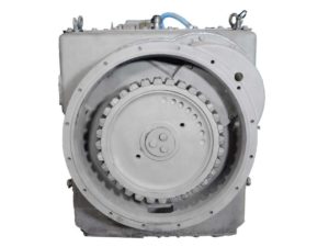
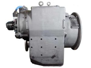
Input Group Assembly For Twin Disc MG-540 Marine Gear
Installing Input Gears and Bearings
Begin with a clean and prepped workspace. Ensure all cleaned components are lightly oiled. Stand the input group with the input end facing upward.
- Install Input Bearing Cups:
- Lubricate the tapered rollers with clean oil.
- Freeze the races if necessary and press them evenly into the housing bores.
- Install Test Shim Pack:
- Place temporary shims on the housing to intentionally leave excess end play for measurement.
- Install the driven gear using a lifting fixture or tool.
- Secure the Retainer:
- Use five 1/2-13 x 1.5 capscrews torqued to 65 lb-ft.
- Rotate the gear several times and use a dial indicator to measure end play.
End Play Measurement and Shim Selection
Use the dial indicator and lift the gear upward, then rotate 720° to measure deflection.
- Target End Play Range: 0.0005–0.003 inches
- Adjust shims until this range is achieved. If unsure, always err slightly toward the lower limit.
- Once proper end play is achieved, remove the test shims and install the final shim stack.
Seal Installation and Housing Preparation
- Install O-Ring on Retainer Pilot and apply light oil to avoid shearing during compression.
- Place the Snap Ring into the driven gear groove to lock in place.
- Reinstall the Retainer and Cover Plate using five 1/2-13 x 1.5 capscrews torqued to 65 lb-ft1.
- Check Pilot and Face Runout using a dial indicator:
- Max face runout: 0.010″
- Max pilot runout: 0.010″
Output Shaft and Bearings For Twin Disc MG-540 Marine Gear
Bearing Cone and Cup Installation (Hot and Cold Techniques)
- Heat Bearings to 250°F if a press is not available.
- Place the shaft vertically with the output end up.
- Install the Tapered Roller Bearings:
- Press or slide the heated bearings over the shaft and seat firmly.
- Do not strike or hammer bearings.
End Play Adjustment and Output Seal Assembly
- Install the output shaft with bearings and rotate to seat components.
- Install a test shim pack and the seal carrier.
- Torque five 1/2-13 x 1.5 capscrews to 65 lb-ft.
- Rotate and lift gear, then read the dial indicator for end play:
- Adjust shim pack to achieve 0.0005–0.003 inches end play.
- Once correct, remove test pack and install final shims.
Installation of Output Gear and Clamp Plate
- Install the output gear onto the tapered shaft using a press or mallet and heat technique.
- Install the clamping plate with three 1-14 x 2 bolts.
- Torque bolts and install locking tabs.
- Bend tabs over bolt flats to lock torque.
Clutch Assemblies (Primary and Secondary) For Twin Disc MG-540 Marine Gear
Piston and Spring Installation
- Install the Piston Seal Ring into the shaft groove.
- Use a clutch compression tool (T-16240-3) to compress the spring.
- Install Retaining Snap Ring and verify it is seated properly.
- Heat clutch hubs to 250°F and install over the shaft spline.
Measuring Clutch Pack Clearance
- Install Friction and Steel Plates:
- Start with a friction plate, then alternate.
- Total: 11 friction + 12 steel + 3 additional steel plates.
- Measure the distance from the piston to the cylinder and from clutch plate to gear face.
- Calculate Released Clutch Clearance:
- Required range: 0.165″ – 0.270″
- Difference between forward and reverse clutch must be ≤ 0.020″
- Add a steel plate if necessary to reduce clearance.
Friction and Steel Plate Stack-Up and Torque Specs
- Lower the shaft and cylinder assembly into the hub.
- Install four equally spaced 1/2-13 x 6 capscrews.
- Torque to 90 lb-ft evenly.
- Manually engage piston against clutch pack and torque to 20 lb-ft.
- Remove the clutch hub after lockup is verified.
- Perform runout checks at three locations:
- Max at point A: 0.005″
- Max at point B: 0.009″
- Max at point C: 0.004″
Manifold and Carrier Installation For Twin Disc MG-540 Marine Gear
O-Ring Placement and Lubrication
- Install o-rings in all manifold recesses using clean oil.
- Avoid using grease that may displace under pressure or heat.
- Verify alignment pins and gaskets are in place on mating surfaces.
Proper Application of Loctite® Sealant
- Apply Loctite® to:
- Rear manifold mating surfaces
- Threads of all 1/2-13 capscrews
- Use a medium-strength (blue) removable threadlocker unless specified
Torque Values for Capscrews
Fastener Size |
Torque (lb-ft) |
Notes |
| 1/2-13 | 83–97 lb-ft | Main housing bolts |
| 5/8-11 | 120–140 lb-ft | Gear clamp fasteners |
| 3/8-16 | 25–29 lb-ft | Screens, retainers |
All bolts must be torqued in a criss-cross pattern and threads must be lubricated with a light oil film).
Control Valve Assembly For Twin Disc MG-540 Marine Gear
GP, EC050, Mechanical, and Electric Valve Options
Mechanical Valve (XB2015A):
- No electronics
- Cable-actuated shifting
- Simple and robust
Electric Valve (1020317):
- Solenoid control
- Works with helm switches or joysticks
- Requires stable voltage
GP Valve With EC050 Module (1020941B):
- Most advanced
- Enables cruise/troll mode and diagnostics
- Receives signals via CANbus and analog inputs
Identifying Valve Types and Installing Components
- Check BOM on transmission nameplate.
- Match control type:
- Mechanical = Manual lever
- EC050 = Includes GP Valve + wiring harness
- Electric = Solenoid body only
- Mount valve using proper gaskets and torque values:
- 1/2-13 socket heads: 65 lb-ft
- 1/2-13 socket heads: 65 lb-ft
- Apply Loctite to threaded ports and sensor fittings.
Basic Wiring Integration for Solenoids, Sensors, and Troll Switch
For EC050 Systems:
- Connect solenoid leads to:
- Terminal 10 = Troll switch input
- Terminal 12 = Ground/reference
- Solenoid Inputs:
- Primary solenoid
- Secondary solenoid
- LED Indicators:
- Green = Ready
- Red = Fault
- Flash = Diagnostic Code
Troll Switch Installation:
- Install manual override or momentary switch at helm
- Wire to EC050 input channel
- Calibrate cruise vs. troll speeds after install
Sensor Integration:
- Shaft speed pickup
- Gear ratio calibration (Cruise mode hold for 9 seconds)
- Oil temperature sensor (optional)
Summary Table: Key Assembly Values and Tools
| Component | Torque (lb-ft) | Special Tool | Notes |
| Clutch Assembly Bolts | 90 | T-16240-3 | Compress clutch spring |
| Output Flange Bolts | 140 | Torque Wrench + Lock Plate | Use Loctite + locking tab |
| Control Valve Screws | 65 | Socket Adapter | Use for GP, Electric, or Mech valve |
| Input Seal Installation | Light taps | T-21552-188/191 | SAE 0 / SAE 00 driver |
| Runout Check Tool | N/A | T-17473 | For face/pilot measurement |
| Bearing Preload Tool | N/A | T-16240-4 | For pinion torque testing |
Videos About Twin Disc Transmissions
6 Reasons Your Twin Disc Transmission Has Low Oil Pressure
7 Reasons Your Twin Disc Transmission Is Overheating
3 Reasons Your Clutch Plates in Your Twin Disc Transmission Are Making Excessive Noise
Bull Gear On A Twin Disc Transmission
Rebuilt Twin Disc Transmissions