

 Free US Calls: 1-888-433-4735
 International: 305-545-5588

The efficiency of a diesel engine hinges significantly on the quality and quantity of air delivered to its cylinders. For Detroit Diesel 53 Series engines, the blower and turbocharger are integral to this process. The blower, a staple of two-stroke diesel engines, guarantees a continuous supply of fresh air, while the turbocharger enhances air pressure, ensuring more efficient combustion. Proper maintenance of these components is essential to maintain optimal engine performance, reduce emissions, and prevent costly repairs.
This comprehensive guide provides a detailed exploration of blower and turbocharger maintenance, offering step-by-step procedures, troubleshooting tips, and best practices tailored to Detroit Diesel 53 Series engines.
Understanding the Role of the Blower and Turbocharger
Blower: Heart of the Two-Stroke Diesel Engine

The blower in a Detroit Diesel 53 Series engine plays a dual role:
- Air Supply: It ensures a constant flow of air into the cylinders to support combustion.
- Scavenging: By expelling exhaust gases from the cylinders, it prepares them for the next intake cycle.
Turbocharger: Boosting Engine Efficiency
The turbocharger compresses incoming air, significantly increasing its density. This process allows more air to enter the cylinders, improving combustion and enabling higher power output. Turbocharging also optimizes fuel efficiency and reduces the engine’s overall emissions.
Signs of Blower or Turbocharger Issues
- Reduced Engine Performance: Power loss or sluggish acceleration.
- Excessive Smoke: Black or blue smoke can indicate improper air-fuel mixing.
- Unusual Noises: Whistling, grinding, or rattling sounds from the turbocharger or blower.
- Increased Fuel Consumption: Inefficient combustion leads to higher fuel usage.
- Oil Leaks: Visible oil around seals or in the intake system.
- Temperature Spikes: Overheating due to restricted airflow or excessive friction.
Blower Maintenance
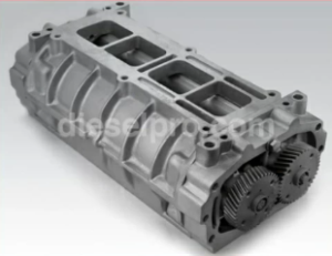
Key Components of the Blower
- Rotors: Ensure smooth airflow into the engine.
- Seals: Prevent oil and air leakage.
- Bearings: Support rotor operation and reduce friction.
- Housing: Encases the blower mechanism.
Routine Blower Inspection
- Visual Examination:
- Inspect for cracks, wear, or corrosion on the housing and rotors.
- Check seals for oil leaks or signs of deterioration.
- Rotational Testing:
- Rotate the blower manually to check for smooth movement. Any resistance, binding, or unusual noises could indicate issues with bearings or rotor alignment.
- Rotate the blower manually to check for smooth movement. Any resistance, binding, or unusual noises could indicate issues with bearings or rotor alignment.
- Clearance Measurement:
- Use a feeler gauge to measure the clearance between the rotors and the housing. Excessive clearance can lead to air leaks and reduced efficiency.
Blower Tolerances for Detroit Diesel 4-53 Engines (353, 453, 6V53, 8V53)
Proper blower rotor clearances are critical to maintaining the efficiency, performance, and longevity of the Detroit Diesel 4-53 engine. This section provides the factory-correct minimum tolerances for rotor-to-housing, rotor-to-end plate, and rotor-to-rotor clearances, as well as gear backlash specifications for the 4-53 engine blower.
Blower Rotor to End Plate Clearances
End plate clearances must be measured with feeler gauges at both the front and rear end plates.
-
Front End Plate Minimum Clearance (4-53):
0.008 inch -
Rear End Plate Minimum Clearance (4-53):
0.009 inch53-Series-Service_Manual
Rotor Lobe to Blower Housing Clearances
Clearances are measured at the inlet and outlet sides of the blower using a feeler gauge across the length of each rotor lobe. Use a specially designed gauge set (J-1698-02) if available.
-
Minimum Clearance at Air Outlet Side (All blowers):
0.004 inch -
Minimum Clearance at Air Inlet Side (In-line engine blower, which includes the 4-53):
0.0075 inch53-Series-Service_Manual
These measurements ensure that the rotors do not contact the housing under thermal expansion or load.
Rotor-to-Rotor Clearances
Clearances are measured between the lobes of the left-hand and right-hand helix rotors using laminated feeler gauges.
-
Minimum Clearance Between Rotors:
0.010 inch53-Series-Service_Manual
Measurements should be taken at three positions:
-
1 inch from each end
-
At the center of the blower
This ensures consistent spacing throughout the entire rotor length.
Rotor Gear Backlash Specifications
The backlash is the clearance between mating gear teeth and must be measured with a dial indicator. Excessive backlash indicates wear and requires gear replacement.
-
New Gear Backlash (Rotor Gears):
0.0005 inch to 0.0025 inch -
Maximum Backlash with Used Gears:
0.0035 inch53-Series-Service_Manual
Note: Rotor gear backlash cannot be adjusted—only the rotor lobe clearances can be adjusted using shims behind the gears.
Blower Drive Gear Backlash (To Camshaft Gear)
This is critical for proper timing and torque transfer from the camshaft.
-
Standard Backlash (4-53 blower drive gear to camshaft):
0.003 inch to 0.007 inch53-Series-Service_Manual
Timing Rotor Gears (Rotor “CC” Clearance)
Proper rotor gear timing is achieved by adjusting shims behind the helical gears. One of the critical measurements during timing is the “CC” clearance.
-
CC Clearance (Trailing edge of RH helix rotor to leading edge of LH helix rotor):
0.008 inch -
C Clearance (Leading edge of RH helix rotor to trailing edge of LH helix rotor):
0.018 inch53-Series-Service_Manual
Summary Table of 4-53 Blower Clearances
Component Minimum Clearance Rotor to front end plate 0.008″ Rotor to rear end plate 0.009″ Rotor lobe to housing (air outlet) 0.004″ Rotor lobe to housing (air inlet) 0.0075″ Rotor to rotor 0.010″ Rotor gear backlash (new) 0.0005″ – 0.0025″ Rotor gear backlash (used) Max 0.0035″ Drive gear backlash to camshaft 0.003″ – 0.007″ “CC” Timing clearance (rotor to rotor) 0.008″ “C” Timing clearance (rotor to rotor) 0.018″
-
- Use a feeler gauge to measure the clearance between the rotors and the housing. Excessive clearance can lead to air leaks and reduced efficiency.
- Check for Debris:
- Inspect the intake path for obstructions or foreign objects. A clogged air filter can cause dirt to enter the blower, damaging the rotors.
- Inspect the intake path for obstructions or foreign objects. A clogged air filter can cause dirt to enter the blower, damaging the rotors.
Blower Disassembly and Cleaning
- Preparation:
-
Ensure the engine is cool and disconnected from power sources.
- Remove any attached air ducts or covers.
-
- Rotor Removal:
- Mark the rotors to ensure proper reassembly.
- Carefully remove the rotors and inspect for wear or damage.
- Housing Cleaning:
- Use a solvent-based cleaner to remove carbon deposits, dirt, and oil residues from the housing. Avoid abrasive tools that could scratch the surface.
- Use a solvent-based cleaner to remove carbon deposits, dirt, and oil residues from the housing. Avoid abrasive tools that could scratch the surface.
- Rotor Cleaning:
- Clean the rotors with a non-abrasive cloth and inspect for cracks or deformations.
- Clean the rotors with a non-abrasive cloth and inspect for cracks or deformations.
Seal and Bearing Maintenance
- Seal Inspection:
- Examine the blower shaft seals for wear or leaks. Replace seals if oil traces are visible near the edges.
- Use only high-quality replacement seals compatible with Detroit Diesel specifications.
- Bearing Replacement:
- Check the blower bearings for noise or roughness when rotated. If damaged, replace with new bearings.
- Apply a thin coat of high-temperature grease to the bearings before installation.
Rotor Timing Adjustment
- Check Rotor Timing:
- Ensure the timing marks on the rotors align correctly to maintain synchronized rotation.
- Ensure the timing marks on the rotors align correctly to maintain synchronized rotation.
- Adjustment Procedure:
- If misaligned, adjust the rotors using the timing gears. Refer to the service manual for precise instructions.
- If misaligned, adjust the rotors using the timing gears. Refer to the service manual for precise instructions.
Reassembly and Testing
- Reassemble the Blower:
- Reinstall the rotors, seals, and bearings in the housing.
- Torque all bolts to the manufacturer’s specifications.
- Test Run:
- Start the engine and observe the blower’s performance. Ensure there are no abnormal noises or vibrations.
- Start the engine and observe the blower’s performance. Ensure there are no abnormal noises or vibrations.
Blower for Detroit Diesel 353 Non – Turbo Marine & industrial Engines
Blower for Detroit Diesel 353 Turbo Marine & Industrial Engines
Blower for Detroit Diesel 453 Non – Turbo Marine & industrial Engines
Blower for Detroit Diesel 453 Turbo Marine & Industrial Engines
Blower for Detroit Diesel 6V53 Non – Turbo Marine & industrial Engines
Blower for Detroit Diesel 6V53 Turbo Marine & Industrial Engines
Blower for Detroit Diesel 8V53 Non – Turbo Marine & industrial Engines
Blower for Detroit Diesel 8V53 Turbo Marine & Industrial Engines
Turbocharger Maintenance
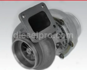
Key Components of the Turbocharger
- Compressor Wheel: Draws in and compresses air.
- Turbine Wheel: Harnesses exhaust energy to drive the compressor.
- Shaft and Bearings: Connect and support the compressor and turbine wheels.
- Wastegate (if applicable): Regulates boost pressure to prevent overcharging.
Routine Turbocharger Inspection
- Visual Inspection:
- Look for cracks, wear, or corrosion on the compressor and turbine housings.
- Inspect for oil leaks around seals and connections.
- Compressor and Turbine Inspection:
- Check the blades for chips, cracks, or deformation.
- Ensure the blades rotate freely without scraping the housing.
- Shaft Play Measurement:
- Use a dial indicator to measure radial and axial shaft play. Excessive play indicates worn bearings or a damaged shaft.
- Use a dial indicator to measure radial and axial shaft play. Excessive play indicates worn bearings or a damaged shaft.
Turbocharger Cleaning
- Compressor Cleaning:
- Remove the compressor housing and clean the blades with a non-abrasive solvent.
- Avoid using wire brushes or harsh chemicals that could damage the blades.
- Turbine Cleaning:
- Clean the turbine housing and blades to remove carbon buildup.
- Use a specialized carbon removal solution for heavy deposits.
Oil and Lubrication System Maintenance
- Oil Line Inspection:
- Check the oil feed and return lines for blockages, leaks, or wear.
- Replace damaged lines to ensure proper lubrication flow.
- Oil Seal Replacement:
- Inspect the turbocharger oil seals for leaks. Replace seals if oil is present in the intake or exhaust system.
- Inspect the turbocharger oil seals for leaks. Replace seals if oil is present in the intake or exhaust system.
- Oil Change:
- Use high-quality engine oil with the specifications recommended by Detroit Diesel.
- Use high-quality engine oil with the specifications recommended by Detroit Diesel.
Turbocharger Balancing and Calibration
- Balancing the Rotating Assembly:
- Ensure the compressor and turbine wheels are balanced to prevent vibrations.
- If necessary, have the turbocharger professionally balanced.
- Boost Pressure Testing:
- Use a boost pressure gauge to verify the turbocharger delivers the recommended pressure. A drop in boost may indicate air leaks, a clogged air filter, or damaged components.
- Use a boost pressure gauge to verify the turbocharger delivers the recommended pressure. A drop in boost may indicate air leaks, a clogged air filter, or damaged components.
Wastegate Maintenance (If Applicable)
- Inspect the Wastegate:
- Check the wastegate for proper operation and adjust as needed to regulate boost pressure.
- Check the wastegate for proper operation and adjust as needed to regulate boost pressure.
- Test the Actuator:
- Ensure the actuator opens and closes smoothly. Replace it if it sticks or fails to respond to pressure changes.
- Ensure the actuator opens and closes smoothly. Replace it if it sticks or fails to respond to pressure changes.
Turbo for Detroit Diesel 353 Turbo Marine & industrial Engines
Turbo for Detroit Diesel 453 Turbo Marine & industrial Engines
Turbo for Detroit Diesel 6V53 Turbo Marine & industrial Engines
Turbo for Detroit Diesel 8V53 Turbo Marine & industrial Engines
Common Issues and Troubleshooting

Blower Issues
- Noise or Vibrations:
- Cause: Misaligned rotors or worn bearings.
- Solution: Realign rotors and replace worn components.
- Reduced Airflow:
- Cause: Clogged intake or excessive rotor clearance.
- Solution: Clean the intake and check rotor clearance.
- Oil Leaks:
- Cause: Worn shaft seals.
- Solution: Replace seals and inspect for shaft damage.
Turbocharger Issues
- Insufficient Boost:
- Cause: Damaged compressor blades or leaks in the intake system.
- Solution: Repair damaged blades and seal any leaks.
- Excessive Smoke:
- Cause: Oil leakage into the intake or exhaust system.
- Solution: Replace oil seals and check for blocked oil return lines.
- High Exhaust Temperatures:
- Cause: Clogged turbine housing or restricted airflow.
- Solution: Clean the turbine and check the air intake system.
Maintenance Best Practices
- Schedule Regular Inspections:
- Check the blower and turbocharger during routine engine maintenance intervals.
- Check the blower and turbocharger during routine engine maintenance intervals.
- Use High-Quality Parts:
- Always use premium aftermarket parts, like those from Diesel Pro Power, for replacements.
- Always use premium aftermarket parts, like those from Diesel Pro Power, for replacements.
- Maintain Clean Air Filters:
- Replace or clean air filters regularly to prevent debris from entering the blower or turbocharger.
- Replace or clean air filters regularly to prevent debris from entering the blower or turbocharger.
- Monitor Oil Quality:
- Use the recommended grade and change oil at specified intervals to prevent contamination.
- Use the recommended grade and change oil at specified intervals to prevent contamination.
- Follow Manufacturer Guidelines:
- Adhere to Detroit Diesel specifications for all maintenance tasks.
- Adhere to Detroit Diesel specifications for all maintenance tasks.