

 Free US Calls: 1-888-433-4735
 International: 305-545-5588
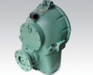
Allison M Rebuilt Marine Transmission
Overhaul Kit & Related Components For Allison M
Allison M Seals
Allison M Clutch Plates
Allison M Hydraulic Pump
Allison M Selector Valve & Related Components
Allison M Bearings & Related Components
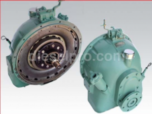
Allison MH Rebuilt Transmission
Allison MH Overhaul Kit & Related Components
Allison MH Seals
Allison MH Clutch Plates & Related Components
Allison MH Hydraulic Pump
Allison MH Selector Valve
Allison MH Bearings & Related Components
Accessing the Clutch Pack
Accessing the clutch pack in Allison M & MH Marine Transmissions is the first critical step in a successful inspection or overhaul. Begin by ensuring that all safety precautions are followed — this includes disconnecting the power source, engaging lockout/tagout procedures, and draining all fluid from the transmission to prevent accidental discharge. Use appropriate PPE, including gloves and eye protection, and work in a clean environment to avoid contamination of clutch surfaces.
Once the external components are removed — including breather caps, selector valve assemblies, and output flanges — you’ll gain visibility into the rear face of the transmission. You must remove the oil pan and drain plugs as described in Section 3 of the Allison manualM MH Series. Access to the clutch is achieved by further disassembling the transmission housing, which may involve lifting or removing the unit from its mount.
The reverse clutch and planetary section is typically the most accessible, while the forward clutch may require removal of the entire input shaft assembly. Be cautious during this process; use a hoist capable of supporting at least ¼-ton weight and sling points as illustrated in the factory diagramsM MH Series.
Wear Patterns and Friction Plate Scoring
Once you’ve accessed the clutch pack, visual inspection is your first diagnostic tool. Examine the friction-faced clutch plates closely. These plates should have a consistent groove depth and minimal scoring. Uneven wear patterns can suggest improper engagement, misalignment, or hydraulic issues within the selector valve.
The Allison service documentation specifies the following wear limits:
- Friction-faced clutch plate thickness: Minimum 0.176 inches (4.47 mm)
- Groove depth minimum: 0.005 inches (0.13 mm)
- Backplate step wear: Max 0.010 inches (0.25 mm)
- Piston step wear: Max 0.010 inches (0.25 mm)M MH Series
Worn plates typically present as heat discoloration, uneven wear on friction surfaces, or signs of flaking or delamination. Scoring is often the result of metallic debris in the hydraulic oil. If this is the case, a thorough flush of the oil system and replacement of all filters is mandatory before reassembly.
Reverse clutch plates are often held within the ring gear by snap rings, and may be backed by return springs. The condition of both the springs and the seating faces is essential for smooth re-engagement and disengagement.
Spring, Disc, and Piston Checks
Your inspection should not stop at friction plates. The entire clutch assembly, including return springs, clutch discs, and pistons, must be evaluated to determine overall health.
Return Springs
For the reverse clutch, 16 springs are used to disengage the clutch during neutral or forward gear operation. Check for:
- Spring fatigue or collapse: Any deviation from standard free height or evidence of heat damage requires replacement.
- Corrosion or scoring: Clean springs must be free of rust or pitting to maintain uniform pressure.
Spring inspection data can be found in Section 8 of the manual, with spring load vs. height values provided for comparisonM MH Series.
Discs
Clutch discs should be perfectly flat and smooth. Warped or deformed discs can result in clutch drag or incomplete engagement. Measurements should be taken across the disc diameter using a micrometer to ensure flatness and confirm OEM thickness specifications.
Pistons
Clutch pistons are critical in hydraulic engagement. They must be smooth, free of corrosion, and their outer sealing surface should be lubricated and undamaged. Key inspection criteria include:
- No pitting or grooves along the piston surface.
- Seal groove depth and diameter conforming to spec.
- Spring tension behind the piston adequate for disengagement.
If glycol or water has entered the transmission (often from a failed cooler), it may chemically attack the friction surfaces and piston seals, in which case both the piston and clutch components must be replacedM MH Series.
Clearance Measurements
To ensure the clutch operates within designed tolerances, precise clearance measurements must be performed. These include:
- Clutch Plate Clearance (End Play): Too little clearance causes clutch drag; too much allows slippage under load.
- Piston-to-Backplate Gap: Measured when disengaged, this indicates if the clutch can fully release.
- Return Spring Compression Height: Assesses whether springs are fatigued or over-compressed.
Use a dial indicator or feeler gauge set to measure these tolerances. Factory specifications generally aim for a clutch pack clearance in the range of 0.030″ to 0.060″, but refer to exact values from wear limits data and assembly foldouts.
Ensure measurements are taken at room temperature and with all components clean, free from oil film or dust, which could skew accuracy.
Reassembly with Proper Preload
After all necessary parts have been replaced or approved for reuse, you must reassemble the clutch pack. This process must follow precise alignment and torque specifications.
Key Reassembly Points:
- Lubricate all components before assembly with oil-soluble grease.
- Install friction plates and steel plates alternately, ensuring tabs align with ring gear grooves.
- Torque the piston assembly into place, ensuring it is flush and centered.
When installing the return springs, make sure spring locations match their original positions to avoid uneven pressure. Insert the snap rings using pliers, ensuring they are fully seated in the groove.
Piston installation must also be supported by preload adjustment. In Allison transmissions, preload is typically achieved by:
- Using shims between the clutch backing plate and piston retainer.
- Measuring compressive preload force to confirm it’s within the prescribed spring compression force in pounds or Newtons.
Use only hand tools when working with Teflon sealrings. Heat in oil baths to 150–200°F (65–93°C) for 15 minutes to ease installation and reduce risk of crackingM MH Series.
Post-Installation Checks
Once reassembled, the clutch pack should undergo several final checks:
- Free rotation: Turn the output shaft and ensure smooth, unimpeded rotation.
- Backlash test: Verify minimal lash between clutch plates and planetary gear train.
- Pressure check: Before reinstalling the unit, simulate hydraulic pressure to confirm clutch engagement with appropriate psi.
Remember, if any metallic noise, grinding, or unexpected friction is detected during test spins, re-inspect for misalignment or missed shims.
Summary of Tools Required
- Micrometer and dial indicator for tolerance checks
- Spring compression gauge
- Sealring installation tool (manual finger tool preferred)
- Bearing press for piston and seal installation
- Torque wrench with appropriate socket set
Common Symptoms of Clutch Failure
Knowing when clutch inspection is required begins with recognizing the symptoms:
- Slipping under load: Often caused by worn friction plates or piston seal leakage.
- Delayed engagement: Indicates poor hydraulic pressure or piston issues.
- Noise during gear change: Can suggest warped discs or misaligned clutch stacks.
- Loss of reverse gear: Frequently caused by broken return springs or worn snap rings in the reverse clutch pack.
Prompt inspection and replacement of worn clutch components can prevent complete transmission failure, especially in high-load marine environments.
Final Thoughts
Allison M & MH Marine Transmissions are engineered with durable, oil-cooled hydraulic clutches designed for years of service under harsh marine conditions. However, the longevity of these systems depends entirely on proper clutch maintenance and timely component replacement.
When inspecting or replacing clutch components:
- Always compare wear measurements to factory specs.
- Replace any friction material that shows uneven wear or scoring.
- Do not reuse fatigued springs or grooved pistons.
- Confirm clutch clearances with precision tools during reassembly.
For More Information
If you require technical guidance for a specific model, please refer to the original Allison M & MH Series Service Manual, or contact a Diesel Pro Power specialist for aftermarket parts, rebuild kits, and expert support for Allison marine transmission models.
Parts such as clutch plates, pistons, sealrings, and spring kits are available at:
Diesel Pro Power – Allison Marine Transmission Parts
Need help now? Our team can walk you through your rebuild step-by-step.
Allison M Rebuilt Marine Transmission
Overhaul Kit & Related Components For Allison M
Allison M Seals
Allison M Clutch Plates
Allison M Hydraulic Pump
Allison M Selector Valve & Related Components
Allison M Bearings & Related Components
Allison MH Rebuilt Transmission
Allison MH Overhaul Kit & Related Components
Allison MH Seals
Allison MH Clutch Plates & Related Components
Allison MH Hydraulic Pump
Allison MH Selector Valve
Allison MH Bearings & Related Components