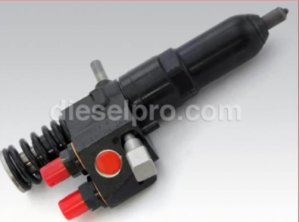
Maintaining optimal injector and valve adjustments is a critical aspect of ensuring the Detroit Diesel 53 Series engines operate at peak efficiency. These adjustments directly affect power output, fuel efficiency, and engine reliability. Below is an exhaustive guide designed to provide precise instructions, clear explanations, and important considerations for performing injector timing and valve adjustments.
Parts Catalog For Detroit Diesel 3-53
Parts Catalog For Detroit Diesel 4-53
Parts Catalog For Detroit Diesel 6V53
Parts Catalog For Detroit Diesel 8V53
Why Injector and Valve Adjustments Are Critical For Detroit Diesel 53 Series Engines (3-53, 4-53, 6V53, 8V53)

- Maintains Power Output: Proper injector and valve timing ensures the engine delivers maximum power by maintaining efficient fuel combustion.
- Improves Efficiency: Correct adjustments reduce fuel wastage, enhance mileage, and lower operational costs.
- Prevents Premature Wear: Minimized mechanical stress on engine components extends service life and prevents breakdowns.
- Reduces Emissions: Ensures cleaner combustion, which helps comply with environmental standards and reduces soot buildup.
Required Tools and Equipment

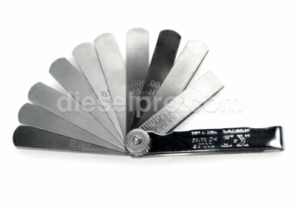
- Feeler Gauges: For measuring valve clearances.
- Injector Height Gauge: Essential for setting injector timing (specific to Detroit Diesel 53 Series).
- Torque Wrench: For applying precise torque to bolts and locknuts.
- Dial Indicator or Timing Pin: For accurately positioning the crankshaft.
- Basic Hand Tools: Screwdrivers, wrenches, socket sets, and pliers.
- Service Manual: For model-specific settings and tolerances.
Preparatory Steps
1. Engine Preparation
- Ensure the engine is off and cool enough to handle safely. Working on a warm engine allows for better adjustments but should not pose safety risks.
- Disconnect the battery to prevent accidental starting.
2. Access the Cylinder Head
- Remove the valve rocker cover using a wrench or socket. Use care to avoid damaging the gasket, and replace it if necessary.
- Clean the area around the cylinder head to prevent debris from entering sensitive components.
3. Position the Crankshaft
- Rotate the crankshaft using a barring tool or a socket on the crankshaft bolt. Alternatively, use the starter motor in short bursts.
- Position Cylinder 1 at Top Dead Center (TDC) on the compression stroke. Verify this using timing marks or a dial indicator.
Injector Timing Adjustment Procedure For Detroit Diesel 53 Series Engines (3-53, 4-53, 6V53, 8V53)

Step 1: Identify Adjustment Position
- Refer to the firing order (e.g., 1-5-3-6-2-4 for the 6V53). Adjust each injector when its corresponding piston is at TDC on the compression stroke.
- The camshaft roller must be positioned on the base circle of the cam lobe.
Step 2: Measure Injector Height
- Place the injector height gauge on the injector follower. The gauge should fit snugly between the follower and injector body.
- If the clearance is incorrect, adjust it using the adjusting screw on the injector rocker arm.
Step 3: Adjust the Injector
- Loosen the locknut on the injector rocker arm adjustment screw.
- Turn the adjustment screw clockwise to decrease clearance or counterclockwise to increase clearance until the height gauge fits securely.
- Hold the adjustment screw in place and tighten the locknut to the manufacturer-specified torque (typically 50-55 lb-ft).
Step 4: Repeat for All Injectors
- Rotate the crankshaft to position the next cylinder at TDC on the compression stroke and repeat the adjustment procedure for each injector.
Injectors & Related Components for Detroit Diesel 353 Non – Turbo Marine & Industrial Engines
Injectors & Related Components for Detroit Diesel 353 Turbo Marine & Industrial Engines
Injectors & Related Components for Detroit Diesel 453 Non – Turbo Marine & Industrial Engines
Injectors & Related Components for Detroit Diesel 453 Turbo Marine & Industrial Engines
Injectors & Related Components for Detroit Diesel 6V53 Non – Turbo Marine & Industrial Engines
Injectors & Related Components for Detroit Diesel 6V53 Turbo Marine & Industrial Engines
Injectors & Related Components for Detroit Diesel 8V53 Non – Turbo Marine & Industrial Engines
Injectors & Related Components for Detroit Diesel 8V53 Turbo Marine & Industrial Engines
Valve Adjustment Procedure For Detroit Diesel 53 Series Engines (3-53, 4-53, 6V53 & 8V53)

Valve adjustments are a critical maintenance task for Detroit Diesel 53 Series engines to ensure proper combustion, efficient operation, and minimized mechanical wear. This expanded guide provides detailed steps and additional context to ensure accurate adjustments.
Step 1: Inspect Valve Components
Examination of Components
- Rocker Arms:
- Inspect for signs of wear or damage, such as scoring, pitting, or excessive play at the pivot points.
- Check for proper lubrication and any indication of overheating or discoloration, which can signal insufficient lubrication.
- Push Rods:
- Roll the push rods on a flat surface to check for bends. A bent push rod can lead to improper valve operation and potential engine damage.
- Inspect the ends of the push rods for signs of wear, flattening, or cracks.
- Valve Bridges (Four-Valve Heads Only):
- Ensure the bridges are not excessively worn or misaligned. A misaligned valve bridge can result in uneven valve operation, leading to performance issues.
Valve Spring Inspection
- Examine the valve springs for fractures, rust, or excessive wear. A damaged or weakened spring can result in improper valve seating, leading to loss of compression and power.
- Measure the spring height and tension:
- Use a spring tester to confirm the spring meets the manufacturer’s specifications.
- Replace any springs that show signs of weakness or failure.
Replacement of Defective Components
- Replace any components showing signs of wear, damage, or misalignment with high-quality aftermarket parts. Using substandard replacements can compromise engine reliability.
Step 2: Measure Valve Clearance
Tools and Preparation
- Tools Required:
- A feeler gauge set with increments as fine as 0.001″.
- A torque wrench for securing components after adjustment.
- Preparation:
- Ensure the engine is cold to achieve accurate measurements. Heat can expand engine components, resulting in incorrect clearances.
Measuring Procedure
- Position the Crankshaft:
- Rotate the crankshaft using a barring tool or socket until the cylinder being adjusted is at Top Dead Center (TDC) on the compression stroke.
- Verify TDC using timing marks or a dial indicator.
- Measure the Gap:
- Insert the feeler gauge between the valve stem and the rocker arm pallet.
- Recommended clearances:
- Intake Valves: 0.013” (cold engine)
- Exhaust Valves: 0.026” (cold engine)
- If the gauge slides through with slight resistance, the clearance is correct. If it is too loose or tight, proceed to adjust.
- Record Findings:
- Document clearances for all valves to identify trends or irregularities during future maintenance.
Step 3: Adjust Valve Clearance
Adjusting the Clearance
- Loosen the Locknut:
- Using a wrench, carefully loosen the locknut on the rocker arm adjustment screw.
- Turn the Adjustment Screw:
- Use a screwdriver to turn the adjustment screw.
- Clockwise to decrease clearance.
- Counterclockwise to increase clearance.
- Adjust until the feeler gauge fits snugly but can still slide between the valve stem and rocker arm.
- Secure the Adjustment:
- Hold the adjustment screw steady with a screwdriver and tighten the locknut to the specified torque (typically 50-55 lb-ft). Use a torque wrench to ensure precision.
Tips for Accurate Adjustment
- Perform adjustments systematically, one valve at a time, to avoid confusion or missed components.
- Always recheck the clearance with the feeler gauge after securing the locknut, as tightening can sometimes alter the setting.
Step 4: Verify the Adjustment
Final Check for Each Valve
- Slide the feeler gauge through the adjusted gap to confirm the clearance is still within specification.
- If adjustments have shifted, repeat the process to ensure accuracy.
Follow the Firing Order
- Proceed to the next cylinder in the engine’s firing order, repeating the measurement and adjustment process for all intake and exhaust valves.
Valve & Related Components for Detroit Diesel 353 Non – Turbo Marine & industrial Engines
Valve & Related Components for Detroit Diesel 353 Turbo Marine & industrial Engines
Valve & Related Components for Detroit Diesel 453 Non – Turbo Marine & industrial Engines
Valve & Related Components for Detroit Diesel 453 Turbo Marine & industrial Engines
Valve & Related Components for Detroit Diesel 6V53 Non – Turbo Marine & industrial Engines
Valve & Related Components for Detroit Diesel 6V53 Turbo Marine & industrial Engines
Valve & Related Components for Detroit Diesel 8V53 Non – Turbo Marine & industrial Engines
Valve & Related Components for Detroit Diesel 8V53 Turbo Marine & industrial Engines
Post-Adjustment Verification For Detroit Diesel 53 Series Engines (3-53, 4-53, 6V53, 8V53)

Rotate the Engine
- Manually rotate the crankshaft through two full revolutions to ensure all components move smoothly without interference.
- Listen for abnormal noises and verify the valves open and close properly throughout the cycle.
Reinstall the Valve Cover
- Inspect the Gasket:
- Check the valve cover gasket for wear, cracks, or deformation. Replace if necessary.
- Secure the Cover:
- Place the valve cover back on the cylinder head and tighten the bolts to the recommended torque to prevent oil leaks.
Test Run
- Start the Engine:
- Observe the engine’s behavior during startup, paying attention to any unusual noises or vibrations.
- Monitor Performance:
- Check for smooth idling and consistent power delivery.
- Look for any signs of improper combustion, such as excessive smoke or misfiring.
- Inspect for Leaks:
- Ensure there are no oil or coolant leaks around the valve cover or cylinder head.
Additional Considerations
Routine Maintenance
- Schedule valve adjustments at regular intervals (every 500 operating hours or as recommended by the manufacturer).
- Combine valve adjustment procedures with other maintenance tasks, such as injector timing or oil changes, to optimize service efficiency.
Use of High-Quality Components
- Replace worn components with premium aftermarket parts, ensuring compatibility with Detroit Diesel 53 Series engines.
Maintenance Records
- Maintain detailed records of valve clearances and adjustments. These logs provide valuable insights into engine health and help track wear trends over time.
Common Issues and Troubleshooting
Problem: Engine Noise (Tapping or Knocking)
- Cause: Improper valve clearance.
- Solution: Recheck and adjust the clearance to specifications.
Problem: Loss of Power or Compression
- Cause: Incorrect valve seating due to excessive clearance or damaged components.
- Solution: Inspect and replace worn valves, guides, or springs. Readjust clearances.
Problem: Excessive Smoke or Fuel Consumption
- Cause: Improper valve timing or clearance.
- Solution: Adjust valve clearance and ensure injector timing is correct.
Best Practices and Maintenance Tips
- Adjust Regularly: Perform injector and valve adjustments every 500 operating hours or as recommended in the service manual.
- Use Quality Parts: Replace worn injectors, valves, and components with high-quality aftermarket parts like those from Diesel Pro Power.
- Maintain Cleanliness: Keep the adjustment area free of dirt and debris to avoid contamination of critical components.
- Document Adjustments: Record clearances, torque values, and other details for future reference and troubleshooting.
- Check Auxiliary Systems: Inspect the fuel system, cooling system, and lubrication system during the tune-up.
Troubleshooting Common Problems
Symptom: Loss of Power
- Cause: Incorrect injector timing or valve clearance.
- Solution: Recheck adjustments and inspect components for wear or damage.
Symptom: Excessive Noise
- Cause: Loose valve lash or improper injector seating.
- Solution: Tighten to specified tolerances.
Symptom: Poor Fuel Efficiency
- Cause: Worn injectors or valves.
- Solution: Replace defective parts and ensure adjustments are precise.
Conclusion
Regular injector and valve adjustments are integral to the maintenance of Detroit Diesel 53 Series engines. These procedures ensure optimal fuel combustion, protect internal components, and sustain the engine’s power and efficiency. By following this comprehensive guide, operators can achieve reliable performance, extend engine life, and minimize downtime. Always consult the service manual for model-specific guidelines and maintain a proactive maintenance schedule.
Parts Catalog For Detroit Diesel 3-53
Parts Catalog For Detroit Diesel 4-53
Parts Catalog For Detroit Diesel 6V53
Parts Catalog For Detroit Diesel 8V53


 Free US Calls: 1-888-433-4735
 International: 305-545-5588