

 Free US Calls: 1-888-433-4735
 International: 305-545-5588

Introduction
The control valve assembly is the command center of the Twin Disc MG516 and MG5161 marine transmissions, managing hydraulic pressure distribution for forward, neutral, and reverse gear actuation. It interprets electronic or manual shift commands and routes pressurized oil to the appropriate clutch pack. If this system becomes clogged, sticky, or electrically faulty, gear engagement becomes delayed, unpredictable, or nonfunctional.
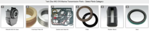
Parts Catalog for Twin Disc MG516 Marine Transmissions
Rebuilt Twin Disc MG516 Marine Transmissions
Plate Kit For Twin Disc MG516 Marine Transmission
Gasket Kits For Twin Disc MG516 Marine Transmission
This guide walks you through:
- The removal and cleaning of solenoids and valve assemblies
- Inspection for contamination, wear, or failure
- Manual and electronic troubleshooting of shift behavior
- Best practices for extending the life of the control valve system
Disclaimer: Always reference the official Twin Disc service manual for component-specific part numbers, torque specs, wiring diagrams, and detailed hydraulic flow paths. This guide is a practical, field-level resource designed to support rebuilders, fleet technicians, and independent marine mechanics.
Overview: How the MG516 Control Valve Works

In the MG516, the control valve:
- Receives shift signals from a manual lever or electronic actuator (e.g., EC300)
- Directs oil pressure from the internal pump to either the forward or reverse clutch piston
- Returns unused oil to the sump or routes it through the cooler
- Controls engagement timing and pressure via internal spools or electric solenoids
The valve must operate precisely under varying conditions. A small amount of contamination or sticking in the control assembly can render the entire marine gear inoperative.
Solenoid and Valve Cleaning for Twin Disc MG516 Marine Gear
When to Service the Valve Assembly
| Condition | Action |
| Delayed or harsh gear shifts | Immediate valve inspection |
| Transmission stuck in gear | Solenoid removal and cleaning |
| Frequent electronic shift alarms | Electrical continuity and resistance test |
| Oil contamination or overheating | Complete valve cleaning |
| Rebuild or transmission removal | Full inspection and seal replacement |
Components in the Control Valve System
- Forward solenoid and valve spool
- Reverse solenoid and valve spool
- Manual override piston (if equipped)
- Control block and housing
- Pressure relief valve or bypass
- Electrical harness or shift cables
- O-rings, dowels, and springs
Diesel Pro Power offers aftermarket valve rebuild kits, O-ring sets, and solenoid assemblies compatible with MG516 configurations.
Tools and Supplies Needed
- Torque wrench
- Electrical multimeter
- Seal pick set and snap ring pliers
- Non-marring pry tools
- Digital caliper or micrometer
- Marine-rated brake cleaner or hydraulic-safe degreaser
- Lint-free cloths
- Light assembly oil or hydraulic-compatible lube
- New O-rings and gaskets
- Thread locker (if specified)
- Workbench with bright lighting
Step-by-Step: Solenoid and Valve Removal
1. Shut Down and De-pressurize System
- Turn off engine and disconnect power source
- Allow transmission to cool
- Relieve hydraulic pressure via the test port if needed
2. Tag and Disconnect Shift Controls
- Label solenoid wires or control cables
- Take a photo of connector orientation
- Disconnect harness or mechanical linkage
3. Drain Oil if Valve Is Side-Mounted
- Oil will spill if valve sits below the reservoir line
- Use appropriate drain pan and absorbent mats
4. Unbolt Valve Body from Housing
- Use correct socket or wrench to avoid stripping bolts
- Remove evenly and store fasteners in labeled tray
5. Remove Solenoids and Valve Spools
- Gently wiggle solenoids free from the control block
- Use clean fingers or pliers to slide out valve spools
- Do not force—components should move smoothly
6. Inspect for Contamination and Scoring
- Examine all bores for:
- Varnish or sludge
- Metal shavings
- Burn marks or discoloration
- Burrs or nicks on sealing surfaces
Cleaning Procedures
A. Solenoids
- Do not submerge electric coils
- Clean external surfaces with non-chlorinated solvent
- Use compressed air to blow out connectors
- Check plunger movement and reinstall O-rings
B. Valve Spools and Ports
- Soak spools in degreaser or brake cleaner
- Scrub with nylon brush
- Rinse and dry completely
- Use micrometer to check spool diameter (no more than 0.001″ wear allowed)
- Inspect spring integrity and plunger action
- Lightly lubricate before reinstallation
Reassembly Tips
- Replace all O-rings with new, correct durometer rubber
- Apply light coating of hydraulic oil to all sealing surfaces
- Install spools in correct orientation—forward vs reverse
- Torque valve housing bolts evenly using OEM pattern
- Reconnect wires or shift linkage and test movement
- Refill transmission oil and prime filter if needed
Testing Shifting Operation for Twin Disc MG516 Marine Gear
Whether the MG516 uses a mechanical lever system or an electronic control module, accurate shift engagement depends on the correct operation of the valve block and its input signals.
Manual Shift Control Systems
Many MG516 units, especially those on workboats or older vessels, use a mechanical cable or rod linkage to actuate the shift valve directly. These systems rely on physical leverage to move spools.
Common Manual Shift Issues
| Symptom | Likely Cause |
| Hard shifting | Misaligned linkage or worn bushings |
| Partial engagement | Cable stretch or bent lever arm |
| Gear skips or slips | Worn detents or cracked valve housing |
| Shift lever stuck | Rusted or jammed spool |
How to Troubleshoot Manual Shifting
- Check Linkage Movement
- Move lever through full range
- Feel for resistance or grinding
- Inspect Cable Mounts and Joints
- Look for corrosion, rust, or dry rotation
- Grease pivot points as needed
- Check Valve Spool Travel
- Disconnect linkage and move spool by hand
- Should move freely with return spring tension
- Measure Lever Throw
- From neutral to forward: full stroke
- From neutral to reverse: symmetrical stroke
Any deviation could result in incomplete clutch engagement and wear.
Electronic Shift Control Systems
Modern MG516 systems often use Twin Disc EC300 or equivalent electronic shift controls. These consist of:
- Electronic shift lever (throttle/gear)
- Control processor
- Shift actuator motor or solenoids
- CAN or analog communication wiring
- Safety interlock and feedback circuits
Common Electronic Shift Faults
Symptom |
Probable Cause |
| Transmission doesn’t shift | Power loss to actuator |
| Delay in engagement | Weak solenoid or electrical lag |
| Error code on controller | Faulty position sensor |
| One gear won’t engage | Bad solenoid or valve sticking |
| All lights flashing | Ground fault or ECU reboot required |
Step-by-Step Electronic Diagnostics
1. Check Power and Ground
- Use multimeter to confirm voltage to actuator harness
- Inspect fuse block and main switch
2. Scan for Error Codes (If Available)
- EC300 and similar systems display codes on head unit
- Reference code list from manufacturer
3. Test Solenoids Manually
- Apply 12V to solenoid pins directly
- Listen for audible click
- No click = faulty coil or plunger stuck
4. Measure Solenoid Resistance
- Use ohmmeter on solenoid terminals
- Normal reading: ~4 to 12 ohms
- Infinite or zero = short or open circuit
5. Test Shift Lever Movement
- Push gear lever into forward and reverse
- Observe actuator movement
- No movement = linkage jam or electrical fault
Simulating Manual Shift
If electronic control fails, some MG516 units allow manual override at the control valve.
- Disconnect linkage or actuator arm
- Insert Allen wrench into shift port
- Rotate gently to simulate spool movement
- Do not force—clutch must not be engaged under load
Manual override is for emergency use only and should be done with the engine off or at idle with prop disengaged.
Preventative Maintenance for Control Valve System
To keep your shift system reliable:
- Change oil every 250 hours to prevent valve varnish
- Inspect solenoids annually for resistance and movement
- Flush control valve block during rebuild or overheating
- Use only correct type oil—detergent oils can cause sticky valve issues
- Clean electrical connectors with dielectric grease
- Secure all wires and linkages to avoid vibration wear
Control Valve Rebuild Kits and Replacement Parts
If the valve body shows any of the following, consider a rebuild:
- Cracks or stripped threads
- Warped valve base
- Pitted or damaged spool bores
- Burned solenoids or melted connectors
- Deformed housing from over-torque
Diesel Pro Power offers aftermarket replacement control valve blocks, solenoids, complete seal kits, and shift lever assemblies compatible with the MG516.
Real-World Shift Troubleshooting Examples
Case Study 1: Commercial Ferry Stuck in Neutral
Symptoms: No engagement in forward or reverse, EC300 flashing
Diagnosis: Forward solenoid burned out
Fix: Replaced solenoid, flushed valve block
Outcome: Full shift function restored
Case Study 2: Trawler with Delayed Reverse
Symptoms: Reverse gear took 5 seconds to engage
Findings: Control spool stuck in bore from varnish
Solution: Removed valve body, cleaned, replaced O-rings
Result: Immediate shift response restored
Case Study 3: Gearbox Slams Into Gear
Issue: Abrupt gear engagement at idle
Cause: Control valve spring lost tension
Action: Installed new spring and spool
Result: Smooth shifting under all conditions
Final Post-Service Checklist
✅ Solenoids tested and reinstalled
✅ Valve bores clean and free of debris
✅ All seals replaced and lightly lubricated
✅ Valve bolts torqued to spec
✅ Shift controls tested (manual or electronic)
✅ Transmission oil topped and system primed
✅ Engine run test completed under load
Summary: Control Valve Maintenance for Twin Disc MG516 Marine Gear
The control valve system of the Twin Disc MG516 is a high-precision hydraulic control center, responsible for smooth and reliable gear engagement. Whether using manual levers or electronic shift actuators, the valve assembly must be clean, calibrated, and free from contamination or wear.
By understanding how to:
- Remove and clean solenoids and internal spools
- Test and troubleshoot manual or electronic shift problems
- Perform voltage and resistance checks
- Identify early signs of wear or failure
Parts Catalog for Twin Disc MG516 Marine Transmissions
Rebuilt Twin Disc MG516 Marine Transmissions
Plate Kit For Twin Disc MG516 Marine Transmission
Gasket Kits For Twin Disc MG516 Marine Transmission
Videos About Twin Disc Transmissions
6 Reasons Your Twin Disc Transmission Has Low Oil Pressure
7 Reasons Your Twin Disc Transmission Is Overheating
3 Reasons Your Clutch Plates in Your Twin Disc Transmission Are Making Excessive Noise
Bull Gear On A Twin Disc Transmission
Rebuilt Twin Disc Transmissions