

 Free US Calls: 1-888-433-4735
 International: 305-545-5588
Parts Catalog for Twin Disc MG5091 Marine Transmissions
Rebuilt Twin Disc MG5091 Marine Transmissions
Plate Kit For Twin Disc MG5091 Marine Transmission
Gasket Kits For Twin Disc MG5091 Marine Transmission
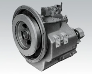
The Twin Disc MG-5091 Marine Gear is built to handle years of high-load, continuous-duty service. But when performance begins to degrade — whether due to slippage, heat, or abnormal noise — it’s time for a detailed inspection and rebuild. A professional-grade disassembly and inspection is the only way to determine internal wear, assess component integrity, and make informed repair decisions.
This article delivers a complete disassembly and inspection guide for the MG-5091, covering required tools, best practices for teardown, safety protocols, and critical wear indicators. By following these procedures, you can prevent improper handling, avoid damaging reusable components, and ensure that only worn parts are replaced.
Disclaimer: Always refer to the official Twin Disc service manual (SM-259) for detailed torque values, tolerances, and hydraulic schematics. The information in this article is intended to help with standard procedures and best practices for aftermarket maintenance and inspection.
Tools Required for Twin Disc MG-5091 Marine Gear
Proper tools are essential to disassemble and inspect the MG-5091 safely and efficiently. Using the wrong tools can damage soft metals, scoring sealing surfaces, or warp housings. Before beginning teardown, assemble all required tools in a clean, organized workspace.
Basic Hand Tools
- SAE socket set (1/4″, 3/8″, and 1/2″ drives)
- Combination wrenches (3/8″ to 1-1/4″)
- Ball-peen hammer and dead-blow mallet
- Snap ring pliers (internal and external)
- Flat-blade and Phillips screwdrivers
- Hex key sets (inch)
Specialty Tools
- Gear puller or hydraulic puller
- For removing bearings, clutch hubs, or gears from shafts
- For removing bearings, clutch hubs, or gears from shafts
- Dial indicator with magnetic base
- Used for measuring backlash, shaft runout, and endplay
- Used for measuring backlash, shaft runout, and endplay
- Feeler gauges
- For soft foot checks and clearance inspection
- For soft foot checks and clearance inspection
- Torque wrench (0–250 ft-lbs range)
- For accurate reassembly of clutch plates, bearing caps, and mount bolts
- For accurate reassembly of clutch plates, bearing caps, and mount bolts
- Bearing race drivers or seal installation tools
- Prevents damage to seal bores and bearing races
- Prevents damage to seal bores and bearing races
- Seal puller or hook tool
- Used to extract output/input shaft seals without scoring the housing
- Used to extract output/input shaft seals without scoring the housing
Safety Equipment
- Steel toe boots and gloves
- Eye protection
- Oil-resistant apron
- Spill containment mats and rags
- Drain pans (minimum 5 gallons)
- Lockout/tagout tags if unit is installed in a vessel
Tip: If you are rebuilding multiple MG-5091 units, invest in a fixture stand or rotating work table to support the transmission during disassembly.
Disassembly Tips for Twin Disc MG-5091 Marine Gear
Disassembling the MG-5091 is a multistage process that requires attention to detail and safe handling of heavy, oil-lubricated parts. Proceed carefully to avoid damaging precision-machined components that may be reused.
Step 1: Draining the Fluid
Draining oil is the first critical step. Failure to drain properly can result in spills, environmental contamination, and slippery workspaces.
Procedure:
- Place drain pan under the transmission.
- Remove the main drain plug from the bottom of the gear housing.
- Remove the dipstick or breather cap to vent air and allow oil to drain completely.
- Allow oil to drain for at least 30 minutes to remove sludge and sediment.
- Inspect drained oil for:
- Metallic flakes (gear wear)
- Milky color (water contamination)
- Burnt smell (clutch overheating)
If the unit has a remote-mounted oil cooler, disconnect and flush all lines before continuing.
Step 2: Removing External Components
Before splitting the gear housing, remove all external accessories.
Components to remove:
- Oil cooler lines (label in/out if reusing)
- Shift control lever or electric shift solenoid
- Oil pressure sensor or switch
- Breather cap
- Dipstick
- PTO (Power Take-Off), if installed
- Output flange bolts and coupler
Label all components for reinstallation.
Step 3: Gear Housing Removal
After fluids and external parts are removed, the main gear housing can be split for internal access.
Steps:
- Remove top cover bolts and carefully lift the inspection cover. Use a gasket scraper to loosen the seal.
- Mark housing halves with a paint marker or center punch to ensure they go back in the correct orientation.
- Remove perimeter bolts around the gear case.
- Use soft-faced mallet to tap along casting joints until separation begins.
- Use lifting straps and hoist if the housing is heavy or stuck.
Never pry open the housing with a screwdriver or chisel — this can damage sealing faces and require re-machining.
Step 4: Clutch Pack and Shaft Removal
With the case open, you can now remove the input and output shafts and clutch assemblies.
Clutch Pack Disassembly:
- Remove retaining rings from clutch drum.
- Carefully pull clutch plates and steel discs one at a time.
- Stack in order for inspection and measurement.
- Inspect pressure plate springs for wear or breakage.
Input/Output Shaft Removal:
- Remove bearing retainer bolts.
- Tap shafts gently using a dead-blow hammer.
- Support shaft weight to avoid nicking the journals.
- Slide shafts out along with associated bearings and gears.
Label each component group to simplify reassembly.
Important: Keep components clean and organized. Use labeled trays or magnetic mats to prevent loss of springs, snap rings, or washers.
Inspection Points for Twin Disc MG-5091 Marine Gear
Once the MG-5091 is fully disassembled, each component must be measured, inspected, and documented. This inspection will determine whether parts can be reused, resurfaced, or replaced. Use precision tools and follow service manual tolerances wherever possible.
1. Clutch Plate Inspection
The clutch pack is a critical wear component and often the reason for disassembly.
What to check:
- Friction material thickness: Must meet OEM spec (usually ≥ 0.050”)
- Heat discoloration: Blue or darkened plates = overheating
- Glazing: Smooth, shiny surfaces reduce friction
- Cracks or chips: Disqualifies reuse
- Flatness: Warped steel plates cause erratic engagement
Measurement Tips:
- Use micrometer to measure stack height
- Compare to service spec for clutch pack clearance
- Replace all plates as a set for balanced engagement
2. Gear Tooth Wear Patterns
Internal gears must be inspected for pitting, cracking, and abnormal contact wear.
Check the following:
- Root pitting: Indicates lubricant failure or contamination
- Tooth surface scoring: Often caused by metal debris
- Gear tooth backlash (see next section)
- Spalling: Metal flaking from surface fatigue
- Excessive wear marks: May indicate misalignment
Minor pitting can sometimes be polished with abrasive cloth, but deep wear or cracks require gear replacement.
3. Backlash Measurement
Backlash refers to the amount of free movement between meshing gears — especially important between input and planetary gear sets.
To measure:
- Mount dial indicator on gear housing.
- Place tip against gear tooth.
- Rotate mating gear back and forth.
- Record Total Indicated Reading (TIR).
Typical backlash values:
- 0.004″ to 0.010″ depending on gear pair
Too much backlash = gear wear
Too little backlash = misalignment or incorrect shimming
4. Shaft Endplay
Shaft endplay is the axial movement of input/output shafts within their bearings.
Procedure:
- Place dial indicator at shaft end.
- Push shaft fully in one direction, zero the gauge.
- Pull shaft in opposite direction and record movement.
Acceptable endplay range:
- Input Shaft: 0.003″ to 0.006″
- Output Shaft: 0.004″ to 0.008″
Excessive endplay can cause poor clutch engagement and seal wear. Correct by adjusting shims or replacing worn bearings.
5. Bearing Inspection
All bearings must rotate freely without noise, looseness, or binding.
Check for:
- Smooth rotation
- Visible pitting or corrosion
- Cracked races
- Discolored balls or rollers (heat damage)
- Looseness in race fits
Use a micrometer or bore gauge to check:
- Bearing journal diameter
- Housing bore for out-of-round condition
Always replace bearings with new when wear is suspected.
6. Seal and Gasket Surfaces
Oil leaks often originate from hardened seals or warped mating surfaces.
What to check:
- Shaft seal lips: Must be flexible and intact
- Seal bore: Clean and smooth, no gouges
- Gasket flanges: Use straightedge to check for warpage
- Bolt holes: No deformation or stripped threads
Replace all seals and gaskets during reassembly, even if they appear usable.
7. Pump and Valve Body
If oil pressure issues were reported, inspect the pump and valve assembly.
Inspection Items:
- Pump gear lash (check against spec)
- Pump housing scoring
- Relief valve movement
- Spool valve freedom of travel
- Solenoid function (if electronic shift)
If housing is scored or gears are worn, the entire pump assembly may need to be replaced.
8. Magnetic Plug and Filter Debris
Reviewing the debris found in your magnetic drain plug and oil filter can reveal the health of your transmission.
| Debris Type | Likely Source |
| Long steel slivers | Gear tooth or bearing failure |
| Fine grey sludge | Normal wear (if minimal) |
| Brass/copper flakes | Clutch hub or bushing wear |
| Black rubber pieces | Seal degradation |
Excessive metal warrants a full overhaul. Small amounts of grey paste on the magnet are normal in break-in periods.
Reassembly Planning and Rebuild Considerations
After a complete inspection, you’ll need to determine which parts can be reused, which must be replaced, and whether a full rebuild is necessary.
Components Typically Replaced in Rebuild:
- All clutch plates and steel discs
- Shaft seals (input/output)
- Bearing sets
- Gaskets and O-rings
- Oil filters
- Damaged gears or hubs
- Worn thrust washers
Components Often Reused:
- Main housing and covers (if undamaged)
- Shafts (if no scoring or runout)
- Valve bodies (unless scored or seized)
- Shift linkage components
Pro Tip: Always clean reused parts in solvent and dry with compressed air. Do not reuse seals, gaskets, or damaged bearings.
Test Before Reinstalling
After reassembly, pressure test the hydraulic system using an external oil pump and gauge to verify:
- No leaks from seals or covers
- Clutch engagement and release
- Steady pressure buildup under load
Install the gearbox only after full verification of pressure, alignment, and engagement response.
Summary
Disassembly and Inspection for Twin Disc MG-5091 Marine Gear
Disassembling and inspecting the Twin Disc MG-5091 is a precision task requiring clean tools, close attention to wear indicators, and accurate measurement. Whether you’re performing a diagnostic teardown or a full rebuild, the steps above ensure safe, successful maintenance with reliable results.
Final Reminders:
- ✅ Use proper pullers, indicators, and torque tools — avoid shortcuts
- ✅ Drain and dispose of fluid safely before removing any covers
- ✅ Label and organize components for seamless reassembly
- ✅ Inspect clutch plates, gears, bearings, and shafts with care
- ✅ Measure backlash and shaft endplay to determine mechanical health
- ✅ Replace all seals and bearings if wear or contamination is detected
Done correctly, this process restores your MG-5091 to factory-level performance — ready for thousands of hours of reliable marine operation.
Parts Catalog for Twin Disc MG5091 Marine Transmissions
Rebuilt Twin Disc MG5091 Marine Transmissions
Plate Kit For Twin Disc MG5091 Marine Transmission
Gasket Kits For Twin Disc MG5091 Marine Transmission