

 Free US Calls: 1-888-433-4735
 International: 305-545-5588

Kona Hawaii fishing boat powered by Detroit Diesel 8.2 L photo provided by James David
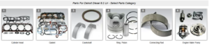
Cylinder Block
Structure and Support Features
The cylinder block is the backbone of the Detroit Diesel 8.2L engine, providing the primary structural framework for all major assemblies. It is a cast-iron design, offering exceptional strength and rigidity. Key structural elements include:
- Webbed Supports: These ensure precise alignment of bearing bores and minimize distortion under load.
- Integrated Water Jackets: Surround all cylinders to maintain optimal operating temperatures and prevent hotspots.
- Oil Galleries: Precision-drilled passages provide efficient lubrication to all moving components, eliminating the need for external piping.
Cleaning, Pressure Testing, and Inspection Procedures
Proper cleaning and inspection are essential before determining the cylinder block’s serviceability:
- Cleaning:
- Remove all external debris using a steam cleaner or solvent tank.
- Ensure internal oil and coolant passages are free from obstructions.
- Pressure Testing:
- Conduct a water jacket pressure test using a block-specific tool, such as J 29671.
- Submerge the block in water and apply 40 psi air pressure, observing for bubbles that indicate cracks or leaks.
- Inspection:
- Use a bore gauge to measure cylinder dimensions for out-of-round or taper.
- Check for cracks, excessive wear, or damage to main bearing bores and mounting surfaces.
Guidelines for Cylinder Block Resurfacing and Repair
Resurfacing ensures a flat mating surface between the cylinder block and head:
- Resurface the block if flatness varies more than 0.003 inches transversely or 0.007 inches longitudinally.
- Maintain a minimum deck height of 12.070 inches from the main bearing bore centerline to prevent interference between pistons and valves.
- After machining, ensure piston protrusion does not exceed 0.026 inches.
If cylinder bores are excessively worn or damaged:
- Honing: Use a honing machine to restore cylinder finish, achieving a crosshatch angle of 22°–32° for proper oil retention.
- Sleeving: For severe damage, install a cylinder sleeve, ensuring a press-fit of 0.0015–0.002 inches.
Cylinder Head
Design and Maintenance
The cylinder head is a single-piece casting that houses intake and exhaust valves, fuel injectors, and their associated mechanisms. Key design features include:
- Injector Tubes: Inserted into water jackets to cool injectors and prevent leaks.
- Heat Shields: Built into exhaust ports to minimize heat transfer to the water jacket.
- Integrated Fuel Gallery: Supplies fuel to injectors through built-in passages.
Maintenance tasks include:
- Regular inspection for cracks around valve seats and water jackets.
- Ensuring proper torque on injector clamps to prevent leaks or cracks.
Common Issues and Troubleshooting
Common cylinder head issues include:
- Overheating: Caused by coolant loss, clogged passages, or faulty thermostats.
- Compression Leaks: Due to warped surfaces or failed gaskets.
- Injector Tube Failures: Resulting in coolant contamination or compression leaks.
Troubleshooting involves:
- Pressure testing the head for leaks.
- Inspecting valve seats and guides for wear or damage.
- Checking torque on bolts and clamps.
Installation and Pre-Installation Inspections
Before installation:
- Clean all mating surfaces and check for flatness.
- Ensure bolt holes are clean and free of debris.
- Replace gaskets and seals, ensuring proper alignment during assembly.
- Tighten bolts to specified torque values using the prescribed sequence to ensure even clamping.
Piston and Connecting Rods

Piston Design and Assembly
Detroit Diesel 8.2L pistons feature:
- Combustion Bowl Design: Enhances air-fuel mixing and combustion efficiency.
- Full Floating Pins: Supported by retainers for smooth articulation.
- Tin Plating: Reduces scuffing and promotes better lubrication during break-in.
Assembly involves installing the piston onto the connecting rod with proper orientation, ensuring that valve reliefs face outward.
Installing and Inspecting Piston Rings
Piston rings are vital for maintaining compression and oil control:
- Compression Rings: Installed with gaps staggered at 120° intervals to prevent blow-by.
- Oil Control Rings: Ensures even oil distribution and minimizes consumption.
Inspection includes checking ring gaps and side clearance using feeler gauges. Rings should fit snugly but not bind within the grooves.
Rebuilding Connecting Rods
Connecting rods undergo stringent inspection for cracks, straightness, and bushing wear. Rebuilding includes:
- Replacing bushings using a press and reaming to precise dimensions.
- Balancing rods to maintain uniform weight distribution.
- Torqueing bearing caps to 59–70 lb-ft and verifying side clearance (0.008–0.020 inches).
Crankshaft and Bearings
Crankshaft Construction and Inspection
The crankshaft is a ductile iron casting with:
- Pressure-Rolled Fillets: Enhances strength and fatigue resistance.
- Oil Drilled Passages: Ensures consistent lubrication to journals and bearings.
- Counterweights: Balances rotational forces for smooth operation.
Inspection involves:
- Checking journals for taper, out-of-round, and surface wear.
- Using magnetic particle inspection to detect cracks.
Installing Crankshaft Main and Connecting Rod Bearings
- Main bearings are installed with grooved shells in the block and plain shells in the caps.
- Connecting rod bearings are similarly matched and torqued to specification.
- Ensure proper alignment by verifying that the crankshaft rotates freely after tightening.
Measuring Wear and Determining Replacement Needs
- Measure bearing clearance using plastigauge or micrometers. Replace if clearance exceeds 0.0056 inches for main bearings or 0.006 inches for connecting rod bearings.
- Inspect for signs of pitting, scoring, or overheating.
Camshaft and Timing Gear
Camshaft Design for Naturally Aspirated and Turbocharged Engines
The camshaft operates valves and injectors through lifters and pushrods. Turbocharged models use a specific camshaft profile, identifiable by a “T” marking, while naturally aspirated models are marked with an “N.”
Timing Gear Alignment and Camshaft Bearing Replacement
Timing gear alignment ensures proper valve and injector timing:
- Align the crankshaft and camshaft gears using their stamped timing marks.
- Replace worn gears and ensure backlash is within 0.003–0.007 inches.
Camshaft bearings are replaced using a driver tool, ensuring proper alignment and lubrication.
Techniques for Machining Camshaft Bearings
When bearings are oversized or misaligned:
- Remove worn bearings and clean the bores.
- Use a boring machine to align the bores and install new bearings.
- Line bore to precise dimensions (2.5665–2.5677 inches) and finish with a smooth surface for optimal performance.
By understanding these major engine assemblies and their service procedures, mechanics can ensure reliable performance and longevity for Detroit Diesel 8.2L engines.