

 Free US Calls: 1-888-433-4735
 International: 305-545-5588
Guide To Tuning Up Your Detroit Diesel 92 Series Engine

In this article we cover a basic tune up for a Detroit Diesel 92 Series engine. Your 92 series engine has no scheduled interval for performing an engine tune-up. As long as the engine’s performance is satisfactory, no tune up should be needed. Minor adjustments to the valve and injector operating mechanism, gover, etc should only be required periodically to compensate for normal wear and tear on parts.
The type of governor used depends on the engine applications. Since the application of the governor has different characteristics, the tune-up procedure varies accordingly. The following types of governors are used.
- Limiting speed mechanical
- Variable speed mechanical
The mechanical governor is identified by the plate attached to the governor housing. The D.W.-L.S. stamped name plate denotes a double-weight limiting speed governor. A single-weight variable speed governor name plate is stamped S.W.-V.S.
Normally, when performing a tune-up on an engine in service, it is only necessary to check various adjustments for a possible change in settings. However, if a cylinder head, governor, or injectors have been replaced or overhauled, then certain preliminary adjustments are required before the engine is started.
The preliminary adjustments consist of the first four items in the tune-up sequence. The procedures are the same except the valve clearance is greater for a cold engine.
Note: If a supplementary governing device such as a throttle delay mechanism is used, it must be disconnected prior to the tune-up. After the governor and the injector rack adjustments are completed, the supplementary governing device must be re-connected and adjusted.
To tune-up an engine completely, perform all of the adjustments in the applicable tune-up sequence given below after the engine has reached normal operating temperature. Since the adjustments are normally made while the engine is stopped, it may be necessary to run the engine between adjustments to maintain normal operating temperature.
Use new rocker cover gaskets after the tune up is completed.
Tune-Up Sequence for Mechanical Governor
Note: Before starting the engine after an speed control adjustment or after removal of the the engine speed control adjustment or after removal of the engine governor cover, the serviceman must determine that the injector racks move to the no fuel position when the governor stop lever is placed in the stop position. Engine overspeed will result if the injector racks cannot be positioned at no-fuel with governor stop lever.
CAUTION: An overspeeding engine can result in engine damage which could result in personal injury.
- Adjusting the exhaust valve clearance
- Time the fuel injectors
- Adjust the governor gap
- Position the injector rack control levers
- Adjust the maximum no-load speed
- Adjust the idle speed
- Adjust the Belleville spring For “TT” horsepower
- Adjust the buffer screw
- Adjust the throttle booster spring (variable governor only)
- Adjust the supplementary governing device if used
Tune-Up Sequence For Hydraulic Governor
- Adjust the exhaust valve clearance
- Time the fuel injectors
- Position the injector rack control levers
- Adjust the governor linkage
- Adjust the load limit screw
- Compensation adjustment (PSG governors only)
- Adjust the speed drop
- Adjust the maximum no-load speed
Full notes about how to tune up your engine can be found in your service manual for Detroit Diesel 92 Series engine.
Detroit Diesel service, repair manual for 6V92, 8V92, 12V92, 16V92
Exhaust Valve Clearance Adjustment For Your 92 Series Engine
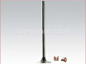
The correct exhaust valve clearance at normal engine operating temperature is important for smooth efficient operation of the engine.
Insufficient valve clearance can result in the loss of compression, misfiring cylinders and, eventually, burned valve seals and valve seal inserts. Excessive valve clearance will result in noisy operation, increased valve face wear and valve lock damage.
Whenever a cylinder is overhauled, the exhaust valves reconditioned or replaced, or the valve operating mechanism is replaced or disturbed in any way, the valve clearance must first be adjusted to the cold setting to allow for normal expansion of the engine parts during the engine warm up period. This will insure a valve setting that is close enough to the specified clearance to prevent damage to the valves when the engine is started.
The exhaust valve bridges must be adjusted and the adjustment screws locked securely at the time the cylinder head is installed on the engine. The necessary adjustment procedure is outlined in Section 1.2.2 of your service manual.
The exhaust valve bridge balance should be checked when general valve adjustment is performed. After the bridges are balanced, adjust the valve clearance at the push rods only.
Do not disturb the exhaust valve bridge adjusting screw.
All of the exhaust valves may be adjusted in firing order sequence during one full revolution of the crankshaft. Refer to the General Specifications section of your service manual for the engine firing order.
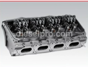
Cylinder Head & Related Components for 6V92 Non- Turbo Detroit Diesel Marine & Industrial Engine
Cylinder Head & Related Components for 6V92 Turbo Detroit Diesel Marine & Industrial Engine
Cylinder Head & Related Components for 8V92 Non- Turbo Detroit Diesel Marine & Industrial Engine
Cylinder Head & Related Components for 8V92 Turbo Detroit Diesel Marine & Industrial Engine
Cylinder Head & Related Components for 12V92 Non- Turbo Detroit Diesel Marine & Industrial Engine
Cylinder Head & Related Components for 12V92 Turbo Detroit Diesel Marine & Industrial Engine
Cylinder Head & Related Components for 16V92 Non- Turbo Detroit Diesel Marine & Industrial Engine
Cylinder Head & Related Components for 16V92 Turbo Detroit Diesel Marine & Industrial Engine
Valve Clearance Adjustment (Cold Engine)
- Remove the loose dirt from the valve rocker covers and remove the covers.
- Place the governor speed control lever in the idle speed position. If a stop lever is provided, secure it in the stop position.
- Rotate the crankshaft, with engine barring tool J 22582 or with the starting motor, until the injector follower is fully depressed on the particular cylinder to be adjusted.
Note: If a wrench of barring tool is used on the crankshaft bolt at the front of the engine, do not turn the crankshaft in a left-hand direction of rotation or the bolt may be loosened.
- Loosen the exhaust valve rocker arm push rod lock nut.
- Place a 0.017” feeler gage, J 9708-01, between the valve bridge and the rocker arm pallet. Adjust the push rod to obtain a smooth pull on the feeler gage.
- Remove the feeler gage. Hold the push rod with a 5/16” wrench and tighten the lock nut with a ½” wrench.
- Recheck the clearance. At this time, if the adjustment is correct, the 0.015” gage will pass freely between valve bridge and the rocker arm pallet, but the 0.017” gage will not pass through. Readjust the push rod if necessary.
- Adjust and check the remaining exhaust valves in the same manner as above.
Valve Clearance Adjustment (Hot Engine)
Maintaining normal engine operating temperature is particularly important when making the final exhaust valve clearance adjustment. If the engine is allowed to cool before setting any of the valves, the clearance when running at full load, may become insufficient.
- With the engine at normal operating temperature (refer to section 13.2 of your service manual), recheck the exhaust valve clearance with feeler gage J 9708-01. At this time, if the valve clearance is correct, the 0.013” gage will pass freely between the valve bridge and the rocker arm pallet, but the 0.015” feeler gage will not pass through. Readjust the push rod, if necessary.
- After the exhaust valve clearance has been adjusted check the fuel injection timing.
Valve & Related Components for 6V92 Non- Turbo Detroit Diesel Marine & Industrial Engine
Valve & Related Components for 6V92 Turbo Detroit Diesel Marine & Industrial Engine
Valve & Related Components for 8V92 Non- Turbo Detroit Diesel Marine & Industrial Engine
Valve & Related Components for 8V92 Turbo Detroit Diesel Marine & Industrial Engine
Valve & Related Components for 12V92 Non- Turbo Detroit Diesel Marine & Industrial Engine
Valve & Related Components for 12V92 Turbo Detroit Diesel Marine & Industrial Engine
Valve & Related Components for 16V92 Non- Turbo Detroit Diesel Marine & Industrial Engine
Valve & Related Components for 16V92 Turbo Detroit Diesel Marine & Industrial Engine
Fuel Injector Timing
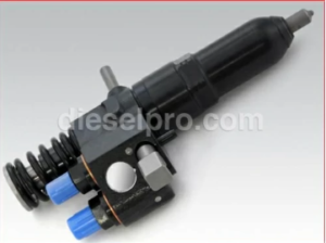
To time an injector properly, the injector follower must be adjusted to a definite height in relation to the injector body.
All of the injectors can be timed in firing order sequence during one full revolution of the crankshaft. Refer to the General Specifications at the front of your service manual for the engines firing order.
Time Fuel Injector

After the exhaust valve clearance has been adjusted, time the fuel injectors as follows:
- Place the governor speed level in the idle speed position. If the stop lever is provided, secure it in the stop position.
- Rotate the crankshaft, with the starting motor or with engine barring tool J 22582, until the exhaust valves are fully depressed on the particular cylinder to be timed.
Note: If a wrench is used on the crankshaft, do not turn the crankshaft in a left-hand direction of rotation or the bolt may loosen.
- Place the small end of the injector timing gage in the hole provided in the top of the injector body with the flat of the gage toward the injector follower.
- Loosen the injector rocker arm push rod lock nut.
- Turn the push rod and adjust the injector rocker arm until the extended part of the gage will just pass over the top of the injector follower.
- Hold the push rod and tighten the lock nut. Check the adjustment and if necessary, re-adjust the push rod.
- Time the remaining injectors in the same manner as outlined above.
- If no further engine tune-up is required, install the valve rocker covers, using new gaskets.
Variable Speed Mechanical Governor And Injector Rack Control Adjustment
The single-weight variable speed governor is mounted at the front of the engine and is driven by a blower rotor.
After adjusting the exhaust valve and timing the fuel injectors, adjust the variable speed mechanical governor and position the rack control levers.
Note: Before proceeding with the governor and injector rack adjustments, disconnect any supplementary governing device. After the adjustments are completed, reconnect and adjust the supplementary governing device.
Adjust Governor Gap
With the engine stopped and at normal operating temperature, adjust the governor gap as follows:
- Disconnect any linkage attached to the governor levers.
- Back out the buffer screw until it extends approximately ⅝” from the lock nut.
- Clean and remove the governor cover and valve rocker covers. Discard the gaskets.
- Place the speed control lever in the maximum speed position.
- Insert a 0.0006” feeler gage between the spring plunger and the plunger guide. If required loosen the lock nut and turn the adjusting screw until a slight drag is noted on the feeler gage.
- Hold the adjusting screw and tighten the lock nut. Check the gap again and, if necessary readjust.
- Use a new gasket and install the governor cover.
Position Injector Rack Control Levers
The position of the injector control rack levers must be correctly set in relation to the governor. Their position determines the amount of fuel injected into each cylinder and ensures equal distribution of the load.
Properly positioned injector rack control levers, with the engine at full load, will result in the following.
- Speed control lever at the maximum speed position.
- Stop lever in the run position.
- High speed spring plunger within 0.005” to 0.007” of its seat in the governor control housing.
- Injector fuel control racks in the full-fuel position.
The letters R and L indicate the injector location in the right or left cylinder bank, viewed from the rear of the engine. The cylinders are numbered starting at the front of the engine on each cylinder bank. Adjust the front of the engine on each cylinder bank. Adjust No 1L injector rack control lever first to establish a guide for adjusting the remaining control levers.
- Remove the clevis pin from the fuel rod and the right cylinder bank injector control tube.
- Loosen all of the inner and outer injector rack control lever adjusting screws on both cylinder heads. Be sure all of the injector rack control levers are free on the injector control tubes.
- Move the speed control lever to the maximum speed position.
- Move the stop lever to the Run position and hold it in that position with light finger pressure. Turn the inner adjusting screw of the No. 1L injector rack control lever down until a slight movement in the stop lever is noted. Turn down the outer adjusting screw until it bottoms lightly on the injector control tube. Then alternately tighten both the inner and outer adjusting screws.
Note: Overtightening of the injector rack control lever adjusting screws during installation or adjustment can result in damage to the injector control tube. The recommended torque of the adjusting screws is 24-36 in-lbs.
IMPORTANT: The above step should result in placing the governor linkage and control tube assembly in the same position that they will attain while the engine is running at full load.
- To be sure of the proper rack adjustment hold the stop lever in the run position and press down on the injector rack with a screw driver or finger tip and note the “rotating” movement of the injector control rack when the lever is in the run position. Hold the stop lever in the run position and, using a screw driver, press downward on the injector control rack. The rack should tilt downward and, when the pressure of the screw driver is released, the control rack should “spring” back upward.
If the rack does not return to its original position, it is too loose. To correct this condition, back off the outer adjusting screw slightly and tighten the inner adjusting screw slightly.
The setting is too tight if, when moving the stop lever from the stop to the run position, the injector rack becomes tight before the stop lever reaches the end of its travel. This will result in a step-up in effort required to move the stop lever to the end of its travel. To correct this condition, back off the inner adjusting screw slightly and tighten the outer adjusting screw slightly.
Note: Overtightening of the injector rack control tube lever adjusting screws during the installation of adjustment can result in damage to the injector control tube. The recommended torque of the adjusting screws is 24-36 in-lbs.
- Remove the clevis pin from the fuel rod and the left-bank injector control tube lever.
- Insert the clevis pin in the fuel rod and the right cylinder bank injector control tube lever and position the No. 1R injector rack control lever as previously outlined in Step 4.
- Insert the clevis pin in the fuel rod and left bank injector control tube lever. Repeat the check on the No 1L and No. 1R injector rack control levers as outlined in Step 5. Carefully observe and eliminate any deflection which occurs at the bend in the fuel rod where it enters the cylinder head.
- To adjust the remaining injector rack control levers, remove the clevis pins from the fuel rods and the injector control tube levers, hold the injector control racks in the full-fuel position by means of the lever on the end of the control tube and proceed as follows.
- Turn down the inner adjusting screw of the injector rack control lever until the screw bottoms (injector control rack in the full-fuel position).
- Turn down the outer adjusting screw of the injector rack control lever until it bottoms on the injector control tube.
- While still holding the control tube lever in the full-fuel position, adjust the inner and outer adjusting screws to obtain the same condition as outlined in Step 5. Tighten the screws.
CAUTION: Once the No. 1L and No1R injector rack control levers are adjusted, do not try to alter their settings. All adjustments are made on the remaining control racks.
10) When all of the injector control rack levers are adjusted, recheck their settings. With the control tube lever in the full-fuel position, echeck each control rack as in Step 5. All of the control racks must have the same “spring” condition with control tube lever in the full-fuel position.
11) Insert the clevis pins in the fuel rods and the injector control tube levers.
Adjust Maximum No-Load Speed
All governors are properly adjusted before leaving the factory. However, if the governor has been reconditioned or replaced, and to ensure the engine speed will not exceed the recommended no-load speed as given on the engine option plate, set the maximum no-load speed as outlined below.
Start the engine and, after it reaches normal operating temperature, determine the maximum no-load speed of the engine with an accurate hand tachometer. Then stop the engine and make the following adjustments, if required:
- Disconnect the booster spring and the governor stop lever spring.
- Remove the variable speed spring housing and the spring retainer located inside the housing from the governor housing.
- Refer to Table 1 and determine the stops or shims required for the desired full-load speed.
- Install the variable speed spring retainer and housing and tighten the two bolts.
- Connect the booster spring. Start the engine and recheck the maximum no-load speed.
- If required, add or remove shims to obtain the desired full load speed. The speed will increase approximately 1rpm for each 0.001” in shims added.
IMPORTANT: If the maximum no-load speed is raised or lowered more than 50rpm by the installation or removal of shims, recheck the governor gap. If readjustment of the governor gap is required, the position of the injector racks must be rechecked.
NOTE: Governor stops are used to limit the compression of the governor spring, which determines the maximum speed of the engine.
Adjust Idle Speed
With the maximum no-load speed properly adjusted, adjust the idle speed as follows:
- Place the speed control lever in the idle position and the stop lever in the run position.
- With the engine running at normal operating temperature, back out the buffer screw to avoid contact with the differential lever.
- Loosen the lock nut and turn the idle speed adjusting screw until the engine is operating at approximately 15rpm below the recommended idle speed.
NOTE: The recommended idle speed is 500rp but may vary with special engine applications.
- Hold the idle speed adjusting screw and tighten the lock nut.
Adjust Buffer Screw
- With the engine running at normal operating temperature, turn the buffer screw in so that it contacts the differential lever as lightly as possible and still eliminates engine roll.
NOTE: Do not raise the engine idle speed more than 15 rpm with the buffer screw.
- Hold the buffer screw and tighten the lock nut.
Adjust Booster Spring
With the idle speed adjusted, adjusted the booster spring as follows:
- Move the speed control lever to the idle speed position
- Loosen the booster spring retaining nut on the speed control lever. Loosen the lock nuts on the eye bolt at the opposite end of the booster spring.
- Move the bolt in the slot of the speed control lever until the center of the bolt is on or slightly over center (toward the idle speed position) of an imaginary line through the bolt, lever shaft and eye bolt. Hold the bolt and tighten the lock nut.
- Start the engine and move the speed control lever to maximum speed position and release it. The speed control lever should return to the idle spring position. If it does not, reduce the tension on the booster spring. If it does, continue to increase the spring tension until it does not return to idle and tighten the lock nut on the eye bolt. This setting will result in the minimum force required to operate the speed control lever.
- Connect the linkage to the governor levers.
No patent liability is assumed with respect to the use of information contained in this blog post. While every precaution has been taken in preparation of this blog post, the author assumes no responsibility for errors and omissions. Neither is any liability assumed for damages resulting from the use of the information contained in this blog post.
All instructions, diagrams, videos have been checked for accuracy and ease of application; however success and safety in working with tools depend to a great extent upon individual accuracy, skill, and caution. For this reason, the authors are not able to guarantee the result of any procedure contained in this blog post. Nor can they assume responsibility for any damages to property or injury to persons occasioned from the procedures. Persons engaging in the procedures do so entirely at their own risk.