

 Free US Calls: 1-888-433-4735
 International: 305-545-5588

Introduction
The Cummins C Series engines (6C, 6CT, and 6CTA) are renowned for their robust performance and durability. Key to maintaining this reliability is proper care of the valve and cylinder head components. These elements play a crucial role in engine efficiency, power output, and longevity. Poor maintenance can lead to performance issues, increased emissions, and costly repairs.
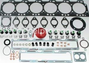
Valve & Cylinder Head & Related Components for Cummins 6C Marine & Industrial Engines
Valve & Cylinder Head & Related Components for Cummins 6CT Marine & Industrial Engines
Valve & Cylinder Head & Related Components for Cummins 6CTA Marine & Industrial Engines
This guide provides comprehensive instructions on:
- How to Remove, Inspect, and Service the Cylinder Head
- Valve Adjustments and Common Cylinder Head Issues
- Recognizing Signs of Damage
By following these guidelines, mechanics and operators can ensure their engines perform optimally.
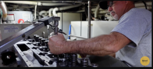
1. How to Remove, Inspect, and Service the Cylinder Head

A. Removing the Cylinder Head
Tools Needed:
- Torque wrench
- Socket set
- Hoist or lifting device
- Engine barring tool
- Valve spring compressor
Step-by-Step Process:
- Preparation:
- Disconnect the battery to prevent accidental starts.
- Drain the coolant and engine oil.
- Remove Engine Components:
- Disconnect fuel lines, air intake ducts, and electrical connections.
- Remove the exhaust manifold and turbocharger if present.
- Detach the valve cover to access the rocker arms and pushrods.
- Remove Rocker Arms and Pushrods:
- Loosen the rocker arm capscrews gradually to avoid bending components.
- Keep track of the pushrod order for reassembly.
- Cylinder Head Removal:
- Loosen the cylinder head bolts in the reverse sequence of the tightening pattern.
- Use a hoist to lift the head off the engine block safely.
B. Inspecting the Cylinder Head

- Visual Inspection:
- Check for cracks, burn marks, and gasket surface damage.
- Inspect coolant passages for corrosion or blockages.
- Flatness Check:
- Use a straight edge and feeler gauge.
- Cylinder head flatness should not exceed 0.20 mm (0.008 in) end-to-end and 0.076 mm (0.003 in) side-to-side.
- Crack Detection:
- Use a magnetic particle crack detector or dye penetrant test.
- Pay attention to areas around valve seats and injector bores.
- Thickness Measurement:
- Measure head thickness with a micrometer.
- Replace the head if it is less than 114.75 mm (4.518 in) thick.
C. Servicing the Cylinder Head

- Cleaning:
- Use a gasket scraper to remove old gasket material.
- Clean carbon deposits with a wire brush or Scotch-Brite pad.
- Valve Seat Grinding:
- Grind valve seats to restore a proper sealing surface.
- Ensure valve seat width is between 1.5 mm (0.059 in) and 2.0 mm (0.079 in).
- Valve Guide Inspection:
- Measure inside diameter with a bore gauge.
- Replace if outside 9.539 mm (0.3756 in) to 9.591 mm (0.3776 in) tolerance.
- Reassembly:
- Install new gaskets, valve seals, and expansion plugs.
- Torque head bolts following the specified sequence and torque values.
Cylinder Head & Related Components for Cummins 6C Marine & Industrial Engines
Cylinder Head & Related Components for Cummins 6CT Marine & Industrial Engines
Cylinder Head & Related Components for Cummins 6CTA Marine & Industrial Engines
2. Valve Adjustments and Common Cylinder Head Issues

A. Valve Adjustment Procedure

Tools Needed:
- Feeler gauge
- Torque wrench
- Engine barring tool
Step-by-Step:
- Locate Top Dead Center (TDC):
- Rotate the crankshaft until cylinder #1 is at TDC on the compression stroke.
- Use the timing pin to lock the position.
- Adjust Valve Clearance:
- Intake valves: 0.30 mm (0.012 in) clearance.
- Exhaust valves: 0.61 mm (0.024 in) clearance.
- Insert the feeler gauge between the valve stem and rocker arm.
- Adjust until slight resistance is felt.
- Tighten Locknuts:
- Torque to 24 Nm (18 ft-lb).
- Recheck clearances after tightening.
- Rotate Crankshaft:
- Turn 360° to adjust the next set of valves.
- Turn 360° to adjust the next set of valves.
B. Common Cylinder Head Issues
- Warping:
- Caused by overheating.
- Results in poor sealing, leading to coolant leaks and compression loss.
- Cracks:
- Develop from thermal stress or improper torqueing.
- Often found around valve seats and injector bores.
- Burnt Valves:
- Occurs due to poor sealing or lean fuel mixtures.
- Leads to loss of compression and power reduction.
- Blown Head Gasket:
- Symptoms include white smoke, coolant loss, and oil contamination.
- Symptoms include white smoke, coolant loss, and oil contamination.
- Valve Seat Recession:
- Caused by excessive heat and poor lubrication.
- Results in improper valve sealing.
Valve & Related Components for Cummins 6C Marine & Industrial Engines
Valve & Related Components for Cummins 6CT Marine & Industrial Engines
Valve & Related Components for Cummins 6CTA Marine & Industrial Engines
3. Recognizing Signs of Damage
A. Symptoms of Cylinder Head Damage
- Overheating:
- Indicates possible head warping or a blown gasket.
- Indicates possible head warping or a blown gasket.
- White Exhaust Smoke:
- Sign of coolant leakage into the combustion chamber.
- Sign of coolant leakage into the combustion chamber.
- Loss of Power:
- May indicate compression leaks due to damaged valves or head cracks.
- May indicate compression leaks due to damaged valves or head cracks.
- Oil Contamination:
- Milky oil suggests coolant mixing due to a blown head gasket.
- Milky oil suggests coolant mixing due to a blown head gasket.
- Hard Starting:
- Can be caused by poor valve sealing.
- Can be caused by poor valve sealing.
B. Diagnostic Techniques
- Compression Test:
- Measures pressure in each cylinder.
- Low compression indicates valve leakage or gasket failure.
- Leak-Down Test:
- Identifies leak sources within the cylinder.
- Identifies leak sources within the cylinder.
- Vacuum Test:
- Tests for valve seat integrity.
- Vacuum must not drop more than 25.4 mm Hg (1 in Hg) in 5 seconds.
- Cylinder Head Pressure Test:
- Submerge in water and apply pressure.
- Look for air bubbles indicating cracks.
- Magnetic Crack Detection:
- Highlights cracks not visible to the naked eye.
- Highlights cracks not visible to the naked eye.
Conclusion
Proper maintenance of the valve and cylinder head systems is vital for the performance, efficiency, and longevity of Cummins C Series engines. Regular inspections, valve adjustments, and prompt attention to signs of damage can prevent costly repairs and ensure reliable engine operation. By following the procedures outlined in this guide, operators and technicians can keep their Cummins engines running at peak performance for years to come.
Valve & Cylinder Head & Related Components for Cummins 6C Marine & Industrial Engines
Valve & Cylinder Head & Related Components for Cummins 6CT Marine & Industrial Engines
Valve & Cylinder Head & Related Components for Cummins 6CTA Marine & Industrial Engines