

 Free US Calls: 1-888-433-4735
 International: 305-545-5588
Introduction: The Art and Science of Precision Adjustment
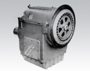
The Twin Disc MG527 Marine Gear is designed for durability, responsiveness, and smooth performance. But even the most robust transmission needs fine-tuning. From shift timing to cable linkage travel, proper adjustments and calibration can be the difference between a vessel that glides smoothly into gear and one that clunks, hesitates, or suffers from premature wear.
Parts Catalog for Twin Disc MG527 Marine Transmissions
Plate Kit For Twin Disc MG527 Marine Transmissions
Rebuilt Gears for Twin Disc MG527 Marine Transmissions
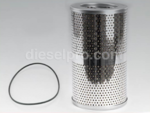
Gasket Kits For Twin Disc MG527 Marine Transmissions
Adjustments are especially important after:
- Gearbox reinstallation or rebuild
- New control cable installation
- A change in electronic or manual control system
- Crew complaints about sluggish shifting or hard engagement
- Evidence of clutch wear or engagement delay
In this guide, we’ll take a deep dive into the calibration procedures and mechanical adjustments required to keep your MG527 running at peak performance. This includes shift timing adjustments, control cable calibration, and best practices for lubricating mechanical linkages. Whether your vessel is used commercially or recreationally, proper setup ensures a longer service life and better handling at the helm.
Section 1: Shift Timing Adjustment for Twin Disc MG527
Understanding Shift Timing
Shift timing refers to how quickly and cleanly the transmission transitions between neutral, forward, and reverse when commanded by the operator. In hydraulic systems like the MG527, this is governed by the pressure buildup in the clutch circuits and the actuation of the control valve—either manually or electronically through a system like the EC300.
Why Shift Timing Matters
Proper shift timing:
- Reduces clutch wear
- Prevents shock loading on the drivetrain
- Enhances maneuverability during docking
- Improves safety for passengers and crew
- Eliminates unnecessary throttle surges or propeller cavitation
Improper shift timing can result in:
- Gear engagement delay
- “Banging” into gear
- Vibration upon shift
- Incomplete clutch lockup
- Overheating due to slippage
When to Adjust Shift Timing
- After a gear rebuild or clutch pack replacement
- When shifting feels too fast (harsh engagement)
- When shifting feels too slow (delayed engagement)
- When changing control systems (manual to EC300 or vice versa)
- After hydraulic pressure issues have been resolved
Shift Timing Adjustment Process (Mechanical Control)
Tools Required:
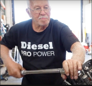
Technician uses a Torque wrench
- Hand tools (for cable or lever adjustments)
- Stopwatch (optional for timing engagement)
- Shift cable alignment tool (if available)
- Dial indicator or linkage travel gauge (optional but helpful)
- Torque wrench
- Marine gear oil and clean rags
Steps:
- Warm Up Transmission
Let the transmission run at idle for at least 10 minutes to bring oil to operating temperature.
- Secure Vessel
Tie off securely and ensure no propeller movement during testing.
- Inspect Linkage Throw
Shift into forward, neutral, and reverse while observing the movement at the gearbox shift arm. Travel should be even, centered, and decisive in all directions.
- Measure Engagement Time
From the moment the shift lever is moved, the time it takes for propeller engagement should be:
- 0.5 to 1.0 seconds (ideal)
- Longer than 1.5 seconds = sluggish
- Less than 0.3 seconds = aggressive/harsh
- Adjust Cable Throw or Lever Position
If travel is too short or not centered, adjust the linkage connection point or bracket:
- Loosen cable bracket bolts
- Slide bracket for better centering
- Retighten bolts securely
- Test at Higher Throttle
Shift at 800–1000 RPM and observe engagement. Do not exceed this speed at dock. Ensure shift time remains consistent.
Shift Timing Adjustment (Electronic Control Systems)
If equipped with a Twin Disc EC300 or other electronic shift system:
- Use the manufacturer’s diagnostic tool to access shift timing parameters
- Connect the interface and follow the calibration wizard
- Many systems allow adjusting soft shift delays or ramp rates
Adjustments include:
- Engagement ramp-up speed
- Hold delays between commands
- Clutch fill delay tuning
Improper calibration in an EC system can result in clutch drag, over-engagement, or complete failure to shift.
Test After Adjustment
- Shift 10 times from forward to reverse at idle
- Listen for any changes in sound or delay
- Run vessel under load (open water if possible) and repeat
Document all timing results and adjustments in your maintenance log.
Section 2: Control Cable and Linkage Calibration For The Twin Disc MG527 Marine Gear
Overview
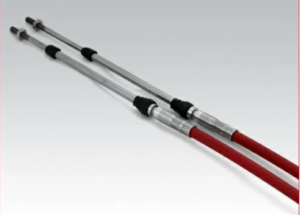
Mechanical control systems use push-pull cables to move the shift lever on the gearbox. Over time, these cables can stretch, bind, or drift out of alignment, causing engagement issues or restricting full clutch engagement.
Correct calibration ensures:
- Full gear engagement in both forward and reverse
- Smooth neutral operation
- No clutch drag when in neutral
- Minimal friction in lever movement
Symptoms of Improper Cable Calibration
- Lever feels stiff or hard to move
- Transmission doesn’t engage even though lever moves
- Partial or slow engagement in one direction
- Gear won’t return cleanly to neutral
- Audible clicking or straining at shift lever
Inspection and Calibration Tools
- Basic hand tools
- Shift cable alignment gauge (optional)
- Ruler or caliper (to measure travel)
- Grease or cable lubricant
- New cotter pins or washers
- Helper (for testing full travel)
Calibration Steps
- Shift to Neutral
Ensure the control handle is in dead-center neutral.
- Inspect Shift Arm Position at Gearbox
Remove engine hatch or cover and locate the shift arm. It should be centered in the gearbox’s neutral detent.
- Disconnect Cable from Shift Arm
Use pliers to remove cotter pin. Slide cable off pivot pin.
- Manually Move Gearbox Lever
Shift the lever into forward and reverse to feel detents and check smoothness. This confirms the gearbox is not the problem.
- Measure Cable Travel
Move shift lever at helm to each gear and measure travel at the gearbox end.- Typical travel should be 2.5–3.0 inches total.
- 1.25–1.5 inches per direction from center.
- Adjust Bracket and Throw
Slide bracket or adjust turnbuckles to align shift cable so that:- Full travel engages both gears completely
- Neutral is centered
- No excessive slack in the cable
- Reconnect and Secure
Reattach the cable with new cotter pins and secure all washers.
Testing Linkage Travel
- Shift from neutral to forward and back ten times
- Do the same in reverse
- Ensure there is no drag, noise, or overshoot
- Recheck engagement time and feel at helm
When to Replace a Shift Cable
- If the cable sheath is cracked, bent, or corroded
- If excessive force is required to move the lever
- If the cable does not hold calibration
- If engagement is inconsistent even after calibration
Use marine-grade stainless steel cables designed for high-heat and high-vibration environments. Cheaper cables wear quickly in marine use.
Section 3: Lubrication of Control Linkage For The Twin Disc MG527 Marine Gear
Proper lubrication ensures smooth movement, accurate engagement, and longer life for control linkages and mechanical shift systems.
Lubrication Points on the MG527 Control Assembly
- Shift arm pivot pin
- Clevis ends of push-pull cable
- Cable sleeve (if serviceable)
- Brackets and guide pulleys
- Helm lever pivot (if stiff)
Lubrication Frequency
| Condition | Lubrication Interval |
| Heavy use (daily ops) | Every 250 hours |
| Seasonal operation | Every 6 months |
| After cable install | After 10 hours, then 100 hours |
| Post-repair | During reassembly |
Approved Lubricants
- Marine lithium grease (water-resistant)
- Synthetic spray lube for pivot joints
- Cable lube with PTFE for inner cable
- Avoid: petroleum jelly, low-temp automotive grease, or silicone sprays—they break down or attract grit.
How to Lubricate Properly
- Clean First
Wipe away old grease, salt buildup, and dirt with parts cleaner.
- Apply Grease to All Pivot Points
Use a small brush or gloved finger to pack grease into shift arm and linkage pins.
- Lube Inside Cable (If Serviceable)
If the cable has zerk fittings or sleeves, inject cable lubricant until clean fluid emerges.
- Cycle the Shift Lever
Move helm and gearbox lever repeatedly to distribute grease evenly.
- Check for Binding
Linkage should move freely without resistance or rebound.
Signs Linkage Needs Lubrication
- Jerky or hesitant shift lever feel
- Loud “clack” when shifting
- Visible corrosion or rust at cable ends
- Cable sleeve discoloration or cracking
- Increased force needed to shift
- Lag between helm movement and gearbox actuation
Calibration Tips From the Field
- Document Everything: Take notes on linkage settings, cable lengths, and adjustment locations. Use a Sharpie to mark bracket positions before changes.
- Use Paint Pens: Once torque is applied or calibration is locked in, paint a line across fasteners to monitor if they shift over time.
- Check in Water: Do a full set of tests dockside, but always confirm under operating load in open water.
- Have a Second Person Help: One at the helm and one in the engine room can drastically speed up adjustments and ensure accurate calibration.
- Watch Your Temps: Gear that’s out of adjustment often runs hotter. Use an infrared thermometer after a test run to monitor housing temps.
Troubleshooting Shift and Linkage Issues
| Symptom | Likely Cause | Fix |
| Delayed engagement | Low pressure or incorrect linkage length | Adjust cable travel or verify pressure |
| Hard shifting | Dry or corroded linkage | Clean and lubricate |
| Gear doesn’t engage | Cable stretched, broken, or misaligned | Replace or recalibrate |
| Doesn’t return to neutral | Linkage binding or control lever issue | Realign or replace cable |
| Gear “pops” out at load | Clutch not fully engaged | Verify cable is reaching full throw |
Maintenance Record Template
Keeping track of adjustments, cable calibrations, and linkage service is essential for long-term reliability. Use the template below to track adjustments.
| Date | Task | Parts Replaced | Notes |
| 2024-03-15 | Calibrated cable | None | Centered neutral detent |
| 2024-03-20 | Lubricated linkage | Grease used: Lucas Marine | Shift feel smoother |
| 2024-06-01 | Adjusted shift delay | EC300 – slowed ramp | Reduced harshness |
Conclusion: Smooth Shifts Start With Smart Adjustments
Properly adjusting and calibrating the Twin Disc MG527 is not just about “feel”—it’s about performance, safety, and the long-term integrity of the gear. Sloppy shifts, harsh engagement, or misaligned controls all create heat, wear, and ultimately cost you time and money.
When you dial in your shift timing, align your cables and linkages, and keep the control system well-lubricated, you unlock the full smooth-shifting power of the MG527. Whether you’re navigating tight marinas, heading offshore, or hauling commercial cargo, responsive gear control means a better ride and a longer-lasting drivetrain.
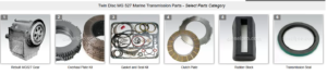
Plate Kit For Twin Disc MG527 Marine Transmissions
Rebuilt Gears for Twin Disc MG527 Marine Transmissions
Gasket Kits For Twin Disc MG527 Marine Transmissions
Videos About Twin Disc Transmissions
6 Reasons Your Twin Disc Transmission Has Low Oil Pressure
7 Reasons Your Twin Disc Transmission Is Overheating
3 Reasons Your Clutch Plates in Your Twin Disc Transmission Are Making Excessive Noise
Bull Gear On A Twin Disc Transmission
Rebuilt Twin Disc Transmissions