

 Free US Calls: 1-888-433-4735
 International: 305-545-5588
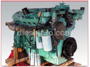
Guide To Engine Tune Up Your 71 V Series Engine Engine

There is no scheduled interval for performing an engine tune-up. As long as the engine performance is satisfactory, no tune-up should be needed. Minor adjustments in the valve and injector operating mechanism, governor, etc. should only be required periodically to compensate for normal wear and tear on parts.
To comply with emission regulations, injector timing, exhaust valve clearance, engine idle and no-load speeds, and throttle delay or fuel modulator settings must be checked and adjusted, if necessary, at 50,000 mile intervals.
Normally, when performing tune-up on an engine in service, it is only necessary to check the various adjustments for a possible change in settings. However, if a cylinder head, governor, or injectors have been replaced or overhauled, then certain tune-up adjustments are required. Accurate tune up adjustments are very important if maximum performance and economy are to be obtained.

NOTICE: If a supplementary governing device such as a throttle delay mechanism is used, it must be disconnected prior to the tune-up. After the governor and injector rack adjustments are completed, the supplementary governing device must be reconnected.
CAUTION: To eliminate the possibility of personal injury when air inlet piping is removed, do not operate an engine with a blower-mounted or front center-mounted turbo charger unless the compressor inlet guard assembly or turbo inlet shield J-26554-A is installed.
Use new valve rocker cover gaskets after the tune-up is completed.
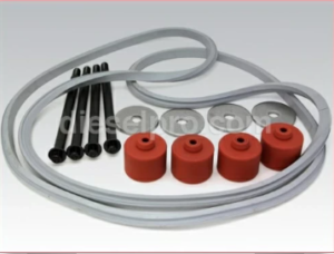
Gaskets & Related Components for 6V71 Non- Turbo Detroit Diesel Marine & Industrial Engines
Gaskets & Related Components for 6V71 Turbo Detroit Diesel Marine & Industrial Engines
Gaskets & Related Components for 8V71 Non- Turbo Detroit Diesel Marine & Industrial Engines
Gaskets & Related Components for 8V71 Turbo Detroit Diesel Marine & Industrial Engines
Gaskets & Related Components for 12V71 Non- Turbo Detroit Diesel Marine & Industrial Engines
Gaskets & Related Components for 12V71 Turbo Detroit Diesel Marine & Industrial Engines
Gaskets & Related Components for 16V71 Non- Turbo Detroit Diesel Marine & Industrial Engines
Gaskets & Related Components for 16V71 Turbo Detroit Diesel Marine & Industrial Engines
Tune Up Sequence for Mechanical Governor

Before starting an engine after an engine speed control adjustment or after removal of the engine governor cover, the service technician must determine that the injector racks move to the no-fuel position when the governor stop lever is placed in the stop position. Engine overspeed will result if the injector racks cannot be positioned at no-fuel with the governor stop lever. An overspeeding engine can result in engine damage which can result in personal injury.
-
Adjust the exhaust valves.
-
Time the fuel injectors.
-
Adjust the governor gap.
-
Position the injector rack control levers.
-
Adjust the maximum no-load speed.
-
Adjust the idle speed.
-
Adjust the Belleville spring for “TT” horsepower.
-
Adjust the buffer screw.
-
Adjust the throttle booster spring.
-
Adjust the supplementary governing device if used.
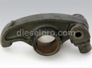
Exhaust Valve Clearance Adjustment
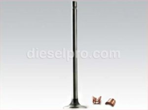
The correct exhaust valve clearance at normal operating temperature is important for smooth, efficient operation of the engine.
Insufficient valve clearance can result in loss of compression, misfiring cylinders and, eventually, burned valve seats and valve seat inserts. Excessive valve clearance will result in noisy operation, increased valve face wear and valve lock damage.
When the cylinder head is overhauled, the exhaust valves are reconditioned or replaced, or the valve operating mechanism is replaced or disturbed in any way, the valve clearance must be adjusted to the cold setting to allow for normal expansion of engine parts during the warm-up period. This will ensure a valve setting that is close enough to the specified clearance to prevent damage to the valves when the engine is started.
All of the exhaust valves may be adjusted in firing order sequence during one full rotation of the crankshaft. Refer to General Specifications at the front of your service manual for the engine firing order.
Service Manual For 6V71, 8V71, 12V71, 16V71 Detroit Diesel Engines
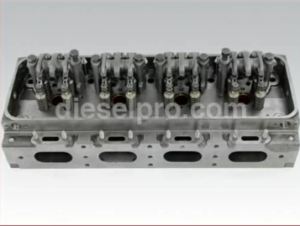
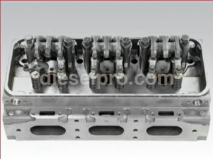
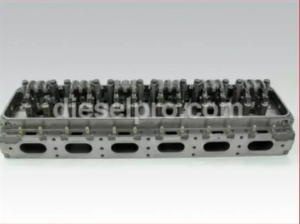
Engines With Four Valve Cylinder Heads
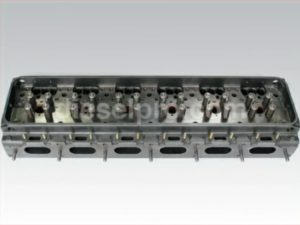
The exhaust valve bridges must be adjusted and the adjustment screws locked securely at the time the cylinder head is installed on the engine
The exhaust valve bridge balance should be checked when a general valve adjustment is performed . After the bridges are balanced, adjust the valve clearance at the push rod only. Do not disturb the exhaust valve bridge adjusting screw.
Valve Clearance Adjustment (Cold Engine)
- Remove the loose dirt from the rocker covers and remove the covers. Discard the gaskets.
NOTICE: On Certain 12V71 Turbocharged engines, it is necessary to remove the air inlet housing to remove the rocker covers.
- Place the governor speed control lever in the idle speed position. If a stop lever is provided, secure it in the stop position.
- Rotate the crankshaft, with engine barring tool J22582 or with the starting motor, until the injector follower is fully depressed on the particular cylinder to be adjusted. If a wrench or barring tool is used on the crankshaft bolt at the front of the engine, do not turn the crankshaft in a left hand direction of rotation because the bolt could be loosened.
CAUTION: To reduce the risk of personal injury when barring over or “bumping” the starter while performing an engine tune-up, personnel should keep their hands and clothing away from the engine as there is a remote possibility the engine could start.
- Loosen the exhaust valve rocker arm push rod locknut.
- Place a 0.016” feeler gage (J 9708-01) between the end of the exhaust valve stem and the valve bridge adjusting screw (spring loaded bridge only) or between the valve bridge and valve rocker arm pallet (unloaded bridge only). Adjust the push rod to obtain a smooth “pull” on the feeler gage.
- Remove the feeler gage. Hold the push rod with a 5/16” wrench and tighten the locknut with a 1/2 “ wrench.
- Recheck the clearance. At this time, if the adjustment is correct, the 0.015” feeler gage will pass freely between the valve stem and the adjusting screw (spring-loaded bridge) or between the valve bridge and rocker arm pallet (unloaded bridge), but the 0.017” feeler gage will not pass through. Readjust the push rod, if necessary.
- Adjust and check the remaining exhaust valves in the same manner as above.
Valve Clearance Adjustment (Hot Engine)
It is not necessary to make final hot engine exhaust valve clearance adjustments after a cold engine adjustment has been performed. However, if a hot engine adjustment is desired, use the following procedures.
Maintaining normal engine operating temperature is particularly important when making the hot engine exhaust valve clearance adjustment. If the engine is allowed to cool before setting any of the valves, the clearance, when running at full load may become insufficient.
NOTICE: Since these adjustments are normally made while the engine is stopped, it may be necessary to run the engine between adjustments to maintain normal operating temperature.
- With the engine at normal operating temperature, recheck the exhaust valve clearance with feeler gage J 9708-01. At this time, if the valve clearance is correct, the 0.013” feeler gage will pass freely between the valve stem and the valve bridge adjusting screw (spring loaded bridge) or between the valve bridge and the valve rocker arm pallet (unloaded bridge), but the 0.015” feeler gage will not pass through. Readjust the push rod, if necessary.
- After the exhaust valve clearance has been adjusted, check the fuel injector timing.
Check Exhaust Valve Clearance Adjustment
- With the engine at 100 degrees fahrenheit (38 degrees celsius) or less, check the valve clearance.
- If 0.016” feeler gage plus or minus 0.004” will pass between the end of the exhaust valve stem and the valve bridge adjusting screw (spring-loaded bridge) or between the valve bridge and the valve rocker arm pallet (unloaded bridge), the valve clearance is satisfactory. If necessary, adjust the push rod.
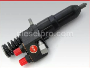
Fuel Injector Timing
To time an injector properly, the injector follower must be adjusted to a definite height in relation to the injector body.
All of the injectors can be timed in firing order sequenced during one full revolution of the crankshaft. Refer to the General specifications section at the front of your service manual.
Service Manual For 6V71, 8V71, 12V71, 16V71 Detroit Diesel Engines
Time Fuel Injector
After the exhaust valve clearance has been adjusted, time the fuel injectors as follows.
- Place the governor speed control lever in the idle speed position. If a stop lever is provided, secure it in the stop position.
- Rotate the crankshaft, with the starting motor or with engine barring tool J22582, until the exhaust valves are fully depressed on the particular cylinder to be timed.
NOTICE: If a wrench or barring tool is used on the crankshaft bolt at the front of the engine do not turn the crankshaft in a left-hand direction of rotation because the bolt could be loosened.
- Place the small end of the injector timing gage in the hole provided in the top of the injector body with the flat of the gage toward the injector follower.
- Loosen the injector rocker arm push rod locknut.
- Turn the push rod and adjust the injector rocker arm until the extended part of the gage will just pass over the top of the injector follower.
- Hold the push rod and tighten the locknut. Check the adjustment and if necessary, readjust the push rod.
- Time the remaining injectors in the same manner as outlined above.
- If no further engine tune-up is required, install the valve rocker covers, using new gaskets.
Variable Speed Mechanical Governor And Injector Rack Control Adjustment
6V71,8V71, AND 12V71 Engines
The single-weight variable speed governor is mounted at the front of the engine and is driven by a blower rotor.
After adjusting the exhaust valves and timing the fuel injectors, adjust the governor and position the injector rack control levers.
Before proceeding with the governor and injector rack adjustments, disconnect any supplementary governing device. After the adjustments are completed, reconnect and adjust the supplementary governing device.
Adjust Governor Gap
With the engine stopped and at normal operating temperature, adjust the governor gap as follows.
- Disconnect any linkage attached to the governor levers.
- Back out the buffer screw until it extends approximately ⅝” from the lock nut.
- Clean and remove the governor cover and valve rocker covers. Discard the gaskets.
- Place the speed control lever in the maximum speed position.
- Insert a 0.006” feeler gage between the spring plunger and the plunger guide. If required, loosen the locknut and turn the adjusting screw until a slight drag is noted on the feeler gage.
- Hold the adjusting screw and tighten the locknut. Check the gap again and if necessary, readjust.
- Affix a new gasket to the top of the governor housing. Place the governor cover assembly on the governor housing with the pin in the stop control shaft assembly in the slot of the differential lever and the dowel pins in the housing in the dowel pin holes in the cover. Tighten the screws.
Injector & Related Components for 6V71 Non- Turbo Detroit Diesel Marine & Industrial Engines
Injector & Related Components for 6V71 Turbo Detroit Diesel Marine & Industrial Engines
Injector & Related Components for 8V71 Non- Turbo Detroit Diesel Marine& Industrial Engines
Injector & Related Components for 8V71 Turbo Detroit Diesel Marine & Industrial Engines
Injector & Related Components for 12V71 Non- Turbo Detroit Diesel Marine & Industrial Engines
Injector & Related Components for 12V71 Turbo Detroit Diesel Marine & Industrial Engines
Injector & Related Components for 16V71 Non- Turbo Detroit Diesel Marine & Industrial Engines
Injector & Related Components for 16V71 Turbo Detroit Diesel Marine & Industrial Engines
Position Injector Rack Control Levers
The position of the injector rack control levers must be correctly set in relation to the governor. Their position determines the amount of fuel injected into each cylinder and ensures equal distribution of load.
Properly positioned injector rack control levers, with the engine at full load, will result in the following.
- Speed control lever at the maximum speed position.
- Stop lever in the run position.
- High-speed spring plunger within 0.005” to 0.007” of its seat in the governor control housing.
- Injector fuel control racks in the *full-fuel position.
The letters “R” and “L” indicate the injector location in the right or left cylinder bank, viewed from the rear of the engine. The cylinders are numbered starting at the front of the engine on each cylinder bank. Adjusting the No. 1L injector rack control lever first to establish a guide for adjusting the remaining control levers.
- Remove the clevis pin from the fuel rod and the right cylinder bank injector control tube lever.
- Loosen all of the inner and outer injector rack control lever adjusting screws or adjusting screws and locknuts on both cylinder heads. Be sure all of the injector rack control levers are free on the injector control tubes.
- Move the speed control lever to the maximum speed position.
- Move the stop lever to the run position and hold it in that position with light finger pressure.
- Move the stop lever to the run position and hold it in that position with light finger pressure.
Two Screw Assembly
Turn the inner adjusting screw of the No. 1L injector rack control lever down until slight movement in the stop lever is noted. Turn down the outer adjusting screw until it lightly bottoms on the injector control tube. Tighten both screws alternately.
One Screw and Locknut Assembly
Tighten the adjusting screw of the No. 1L injector rack control lever until the rack clevis rolls up or resistance increases. Turn the screw approximately ⅛ turn more and secure with the locknut. This sets the No. 1L injector rack in the full-fuel position.
NOTICE: Avoid overtightening the injector control lever adjusting screws, which can damage the control tube. Recommended torque: 24-36 lb-in (3-4 N*m).
To confirm proper adjustment, hold the stop lever in the run position and press the injector rack. The rack should rotate downward and spring back when released.
-
If the rack does not return:
- Two Screw Assembly: Loosen the outer screw slightly and tighten the inner screw.
- One Screw and Locknut Assembly: Loosen the locknut, turn the screw clockwise slightly, and retighten.
-
If the rack becomes tight before the stop lever reaches the run position:
- Two Screw Assembly: Loosen the inner screw slightly and tighten the outer screw.
- One Screw and Locknut Assembly: Loosen the locknut, turn the screw counterclockwise slightly, and retighten.
This adjustment ensures proper governor linkage and control tube positioning for full-load operation.
-
Remove the clevis pin from the fuel rod and the left back injector control tube lever.
- Insert the clevis pin in the fuel rod and the right cylinder bank injector control tube lever and position the No 1R. Injector rack control lever as previously outlined in Step 4.
- Insert the clevis pin in the fuel rod and the left bank injector control tube lever. Repeat the check on the No. 1L and No. 1R injector rack control levers as outlined in Step 5. Carefully observe and eliminate any deflection which occurs at the bend in the fuel rod where it enters the cylinder head.
- To adjust the remaining injector rack control levers, remove the clevis pins from the fuel rods and the injector control tube levers, hold the injector control racks in the *full-fuel position by means of the lever on the end of the control tube and proceed as follows:
Two Screw Assembly
- Turn down the inner adjusting screw of the No. 2L injector rack control lever until it bottoms (full-fuel position).
- Turn down the outer adjusting screw until it bottoms on the injector control tube.
- While holding the control tube lever in the full-fuel position, adjust both screws to match Step 5 conditions. Tighten the screws.
NOTICE: Avoid overtightening; excessive torque can damage the injector control tube. Recommended torque: 24-36 lb-in (3-4 N*m).
One Screw and Locknut Assembly
- Tighten the adjusting screw until the injector rack clevis rolls up or resistance increases.
- Securely lock the adjusting screw nut.
NOTICE: Overtightening can damage the injector control tube. Recommended torque: 24-36 lb-in (3-4 N*m).
Final Verification & Adjustment
- Verify No. 1L injector rack adjustment per Step 5. If it does not “spring” back, turn No. 2L adjusting screw counterclockwise slightly until No. 1L returns to full-fuel position, then secure the locknut.
- Adjust remaining injectors using Step “b,” always verifying rack adjustment.
- Once No. 1L and No. 1R are set, do not alter their settings; all further adjustments are made on the remaining racks.
- When all injector racks are adjusted, recheck settings:
- With the control tube lever in full-fuel position, ensure all racks “spring” back equally.
- With the control tube lever in full-fuel position, ensure all racks “spring” back equally.
- Insert clevis pins in the fuel rods and injector control tube levers.
CAUTION: Before starting the engine, confirm that the injector racks return to the no-fuel position when the governor stop lever is in the stop position. Failure to do so can cause engine overspeed, leading to potential engine damage and personal injury.
- Reinstall valve rocker covers using new gaskets.
Adjust Maximum No-Load Speed
- Check Initial Speed: Start the engine, let it reach normal operating temperature, and measure the maximum no-load speed using a hand tachometer.
- Prepare for Adjustment: Stop the engine, disconnect the booster spring and governor stop lever spring, then remove the variable speed spring housing and retainer.
- Adjust Speed:
- Refer to Table 1 for required stops/shims based on desired full-load speed.
- Each 0.001” shim increases speed by approximately 1 rpm.
- No-load speed is 125-200 rpm above full-load speed.
- Reassemble & Verify: Reinstall the spring retainer and housing, reconnect the booster spring, restart the engine, and recheck speed.
- Fine-Tune if Necessary: Add or remove shims as needed. If adjusting by more than 50 rpm, recheck governor gap and injector rack positions.
Adjust Idle Speed
- Set the speed control lever to idle and stop lever to run.
- With the engine at normal temperature, back off the buffer screw.
- Loosen the locknut and turn the idle speed adjusting screw to set speed 15 rpm below the recommended 500 rpm.
- Hold the screw and tighten the locknut.
Adjust Buffer Screw
- With the engine running, turn the buffer screw until it lightly touches the differential lever and eliminates engine roll.
- Ensure idle speed does not increase by more than 15 rpm.
- Hold the screw and tighten the locknut.
Adjust Booster Spring
- Move the speed control lever to idle.
- Loosen the booster spring retaining nut and eyebolt locknuts.
- Adjust the bolt in the slot of the speed control lever until slightly over center toward idle, then tighten the locknut.
- Start the engine, move the speed control lever to max speed, then release it:
- If it does not return to idle, reduce spring tension.
- If it returns too easily, increase spring tension, then back off just enough to allow return to idle.
- Tighten the eyebolt locknut to finalize the setting.
Final Step: Connect linkage to governor levers.
Variable Speed Mechanical Governor & Injector Rack Control Adjustment (16V71 Engines)
The governor on the 16V71 engine is mounted on and driven from the front end of the rear blower. After adjusting exhaust valves and timing fuel injectors, adjust the governor and injector rack control levers.
Align Control Link Levers Before Engine Tune-Up
If the engine/governor was overhauled or the injector control linkage was disturbed, align the control link levers in the governor and auxiliary control link housings:
-
Prepare for Alignment:
- Disconnect linkage to the governor speed control.
- Remove governor and auxiliary control link housing covers.
- Disconnect the adjustable link from the auxiliary control link lever.
- Remove the connecting pin from the auxiliary governor control link lever.
-
Set Lever Positions:
- Install gage J21779, ensuring it extends through the lever, fuel rod, and housing gage hole. This places the auxiliary control link lever in mid-travel position.
- Remove the connecting pin from the governor housing control link lever and install gage J21780, ensuring the pin extends through the connecting link, control lever, and fuel rod, with the governor housing dowel pin in the gage hole. Secure the gage with a governor cover bolt.
-
Finalize Alignment:
- The governor control link lever should now be parallel to the auxiliary control link lever.
- Adjust the connecting link to maintain lever positions, then reinstall the link.
- Remove gages J21779 & J21780, reinstall control link lever pins, and replace housing covers.
Proceed with governor and injector rack control adjustment.
Governor Gap & Injector Rack Control Adjustment
Adjust Governor Gap
- Preparation: Stop the engine, remove and discard governor/valve rocker cover gaskets.
- Back out the buffer screw ⅝” from the locknut.
- Set the speed control lever to maximum speed.
- Insert a 0.006” feeler gage between the spring plunger and plunger guide.
- Adjust the screw until slight drag is felt, then tighten the locknut.
- Install a new gasket, align the governor cover assembly, and tighten screws.
Position Injector Rack Control Levers
Proper adjustment ensures even fuel distribution. The No. 4R injector control lever is set first, guiding the rest.
-
Preparation:
- Remove clevis pins from both fuel rods.
- Loosen all injector rack control lever screws or locknuts so levers move freely.
- Set the speed control lever to max speed and hold the stop lever in the run position.
-
Adjust No. 4R Injector Rack Control Lever:
- Two Screw Assembly: Tighten the inner screw until slight stop lever movement is noted. Tighten the outer screw until it bottoms lightly, then alternately secure both screws.
- One Screw & Locknut Assembly: Tighten the adjusting screw until the rack clevis rolls up or resistance increases. Turn ⅛ of a turn more and secure the locknut.
NOTICE: Do not overtighten; it may damage the injector control tube. Torque: 24-36 lb-in (3-4 N*m).
Verify Proper Rack Adjustment
- Hold the stop lever in the run position and press down on the injector rack.
- The rack should tilt down and spring back when released.
- If the rack does not return:
- Two Screw Assembly: Loosen outer screw slightly, tighten inner screw.
- One Screw & Locknut Assembly: Loosen locknut, turn screw clockwise slightly, and retighten.
This ensures correct governor linkage and control tube positioning for full-load operation.
Injector Rack Adjustment
Correcting a Tight Setting
If the injector rack tightens before the stop lever reaches the run position, adjust as follows:
- Two Screw Assembly: Loosen the inner screw slightly, tighten the outer screw.
- One Screw & Locknut Assembly: Loosen the locknut, turn the adjusting screw counterclockwise slightly, then retighten.
Adjusting No. 5R & 4L Injector Racks
- Swap Clevis Pin: Move the fuel rod clevis pin from the right front bank to the right rear bank.
- Adjust No. 5R injector rack following Steps 4 & 5.
- Repeat for No. 4L injector rack. When properly adjusted, No. 4R, 5R, 4L, and 5L racks should be snug on the ball end of the control levers in the full-fuel position.
Adjusting Remaining Right Front Bank Injectors
- Hold No. 4R injector rack in the full-fuel position with the control tube lever.
- Adjust No. 3R injector rack control lever:
- Two Screw Assembly: Turn the inner screw until the rack reaches full-fuel. Turn the outer screw until it bottoms lightly, then tighten both screws alternately.
- One Screw & Locknut Assembly: Tighten the adjusting screw until the rack clevis rolls up or resistance increases. Turn ⅛ of a turn more and secure with the locknut.
NOTICE: Avoid overtightening; excessive torque (24-36 lb-in / 3-4 N*m) may damage the injector control tube.
Verification & Final Adjustments
- Recheck No. 4R Injector Rack:
- If loose, adjust No. 3R injector rack:
- Two Screw Assembly: Loosen inner screw slightly, tighten outer screw.
- One Screw & Locknut Assembly: Loosen locknut, turn adjusting screw counterclockwise, then retighten.
- If loose, adjust No. 3R injector rack:
- Ensure No. 3R and 4R injector racks respond identically when the control tube lever is held in full-fuel position.
- Adjust all remaining injectors following Step B, verifying proper alignment after each adjustment.
Final Injector Rack Adjustment & Safety Check
- Adjust Remaining Racks: Set the remaining injector rack control levers on the right front cylinder bank as per Steps 8 & 9.
- Adjust the right rear, left front, and left rear cylinder banks using the same method.
- Secure & Verify: Install the four clevis pins and check injector rack lever adjustments.
CAUTION: Before starting the engine, ensure injector racks return to the no-fuel position when the governor stop lever is in stop. Failure to do so can cause engine overspeed, leading to severe damage and personal injury.
- Reassemble: Install new gaskets and reinstall valve rocker covers.
Adjust Maximum No-Load

Governor & Idle Speed Adjustment
Set Maximum No-Load Speed
If the governor has been reconditioned or replaced, adjust as follows:
- Check Initial Speed: Start the engine, let it reach normal temperature, and measure the maximum no-load speed with a hand tachometer.
- Prepare for Adjustment: Stop the engine, disconnect booster spring and governor stop lever spring, then remove the variable speed spring housing and plunger.
- Adjust Speed:
- Refer to Table 2 for the required stops or shims.
- Each 0.001” shim increases speed by 1 rpm.
- No-load speed is 150-225 rpm above full-load speed.
- Reassemble & Verify: Reinstall the spring plunger and housing, reconnect the booster spring, restart the engine, and recheck speed.
- Fine-Tune if Needed: Add/remove shims as necessary. If adjusting by more than 50 rpm, recheck the governor gap and injector racks.
Adjust Idle Speed
- Set the speed control lever to idle and the stop lever to run.
- With the engine at normal temperature, back out the buffer screw.
- Adjust the idle speed screw to 15 rpm below recommended 550 rpm.
- Hold the screw and tighten the locknut.
Adjust Buffer Screw
- Turn the buffer screw inward until it lightly contacts the differential lever and eliminates engine roll.
- Do not raise idle speed by more than 15 rpm.
- Hold the screw and tighten the locknut.
Adjust Booster Spring
- Move the speed control lever to idle.
- Loosen the booster spring retaining nut and eyebolt locknuts.
- Adjust the bolt in the slot until slightly over center toward idle, then tighten the locknut.
- Start the engine, move the speed control lever to max speed, then release:
- If it does not return to idle, reduce spring tension.
- If it does, gradually increase tension until it won’t return, then back off slightly and secure the locknut.
- Reconnect linkage to governor levers.
Disclaimer
While all instructions, diagrams, and videos have been checked for accuracy, results depend on skill, caution, and precision. The author assumes no liability for errors, damages, or injuries resulting from these procedures. Use at your own risk.
I have a limiting g speed governor. On an 8V71 in a 1962 Hutkins boat that won’t go completely into full load. How to adjust full load? I usually deal with variable speed governor in marine engineering. Thanks, Jesse.