

 Free US Calls: 1-888-433-4735
 International: 305-545-5588
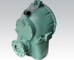
Allison M Rebuilt Marine Transmission
Overhaul Kit & Related Components For Allison M
Allison M Seals
Allison M Clutch Plates
Allison M Hydraulic Pump
Allison M Selector Valve & Related Components
Allison M Bearings & Related Components
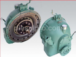
Allison MH Rebuilt Transmission
Allison MH Overhaul Kit & Related Components
Allison MH Seals
Allison MH Clutch Plates & Related Components
Allison MH Hydraulic Pump
Allison MH Selector Valve
Allison MH Bearings & Related Components
Inspecting and Adjusting Shift Linkage
Smooth and accurate shifting is essential to the proper operation of Allison M & MH marine transmissions. These transmissions rely on mechanical linkage that translates motion from the operator’s control station (such as a cockpit shift lever) to the selector valve within the transmission. To ensure consistent gear engagement and to avoid unnecessary clutch wear, the shift linkage must be inspected and properly adjusted at regular intervals or anytime performance anomalies are detected.
Begin by visually inspecting the entire length of the shift linkage. Look for signs of corrosion, deformation, or wear. Check that the linkage is free from obstructions and that all cable routing maintains proper clearance from moving parts, heat sources, and sharp edges. The linkage should not be bent or kinked. Pay close attention to the pivot points, clevis pins, and fasteners—any play or looseness at these junctions can introduce slack and affect shift precision.
Ensure that the shift lever moves freely through its range—forward, neutral, and reverse—and that each detent clicks crisply into place. Detents should be felt clearly, as they correspond to internal valve positioning within the selector valve assembly. Excessive force or vague shifting often indicates either mechanical misalignment or internal hydraulic issues. To isolate the cause, manually operate the transmission’s selector lever at the tower (transmission-mounted end) and observe whether the gear positions are reached consistently.
When adjusting the linkage, the engine should be off and the transmission at ambient temperature to prevent injury. Begin by aligning the cockpit lever to its neutral position, then disconnect the linkage at the transmission. Manually set the transmission selector to neutral and reconnect the linkage without applying preload. If necessary, adjust the threaded rod ends or cable tension until the mechanical neutral at the lever matches the detent at the transmission. This alignment must be confirmed at all three positions—forward, neutral, and reverse.
Final tightening of the linkage components must follow torque specifications for each model, and threadlocker may be applied to prevent loosening due to vibration. After reassembly, cycle through all gear positions again and ensure full travel and accurate engagement.
Free-Play and Detent Engagement
Free-play in a marine transmission’s shift linkage can significantly compromise transmission function. Free-play is defined as the range of shift lever motion that does not result in any movement within the selector valve. Excessive free-play can delay clutch engagement, lead to incomplete gear shifts, and increase wear on internal components.
To assess free-play, gently move the cockpit shift lever back and forth while observing the transmission end of the linkage. Any motion that does not translate to selector valve movement is considered free-play. Specifications vary by model and application, but a general rule is to allow no more than 0.5 to 1.0 degree of free-play at the shift tower.
Adjustments may require repositioning the shift cable mounts or adjusting clevis length. Always verify that the detent engagement aligns with the mechanical stops. When shifted into forward or reverse, the transmission must be fully seated in that gear, with oil pressure confirmed at operating levels.
It is also important to confirm that detents remain crisp and tactile. If the shift lever feels mushy, or if it floats between positions, it may indicate worn detent springs or internal valve body issues. For such cases, inspect the selector valve assembly and replace components as needed using the procedures detailed in the rebuild section of the service manualM MH Series.
Correct Neutral and Gear Alignment
Neutral alignment is critical not only for operational safety but also to prevent unnecessary clutch drag or misalignment within the selector valve. In Allison M & MH marine transmissions, the neutral position corresponds to a hydraulic dead zone where no clutch (forward or reverse) is engaged.
To correctly set neutral:
- With the engine off and battery disconnected, place the cockpit lever in the middle detent position.
- At the transmission, observe the selector lever and ensure it aligns with the neutral detent marked on the selector housing.
- If the detent doesn’t line up, adjust the linkage length until the detents match. This may involve minor thread adjustments or repositioning cable mounts.
After neutral is confirmed, shift to forward and reverse to ensure engagement positions are reached without stressing the cable or compressing linkage components.
Cable slack should be zero at each gear position without exerting stress on the selector lever. Overextension of the cable in either direction can cause internal wear or detent override. Likewise, under-travel may leave the selector valve in an ambiguous position—engaging neither clutch properly.
In twin-engine vessels or installations with complex controls (e.g., dual-station helm setups), ensure synchronization of both controls. This may involve using a dual-output shift synchronizer mechanism or custom cable balancing.
Replacing Worn Bushings or Cables
Over time, bushings and shift cables degrade due to mechanical stress, saltwater exposure, and temperature fluctuations. Indicators of worn components include sticky lever action, inconsistent gear engagement, audible squeaking, or visible cracking of cable sheathing.
Bushings
Shift bushings are typically found at pivot points, mounting brackets, and within lever housings. A worn bushing can lead to radial movement, which introduces alignment errors and contributes to gear grinding or missed shifts.
Replacement involves:
- Disassembling the linkage at the wear point.
- Pressing or tapping out the worn bushing using a bushing removal tool or socket.
- Cleaning the bore with a solvent and installing a new marine-grade, corrosion-resistant bushing.
Cables
Marine shift cables are either solid wire-in-sheath types or multi-strand designs. When replacing a cable:
- Record the original cable length, routing, and mounting locations.
- Detach the cable at both ends, noting washer and bracket orientation.
- Pull the old cable out, feed the new one in reverse order, and secure it to mounts using locking fasteners or cable clamps.
- Lubricate the cable ends with waterproof marine grease before final connection.
Cables should always be routed with gentle bends (minimum 8-inch radius), avoiding sharp curves, kinks, or proximity to heat sources like manifolds or turbochargers. Cable ends must be secured to prevent rattling or loosening during vibration. After replacement, retest for full range of motion, absence of slack, and precise detent engagement.
Verifying Cockpit-to-Transmission Shift Timing
A final and essential step in ensuring proper transmission operation is confirming that the cockpit shift command results in synchronized response at the transmission end. This verification ensures that the entire shift system—from control lever to internal selector valve—is operating in harmony.
To perform shift timing verification:
- Place the cockpit lever in neutral. Have a technician positioned at the transmission to confirm that the selector lever is also in neutral.
- Simultaneously shift into forward, then reverse. Each gear change at the helm should correspond instantly with selector movement at the transmission.
- With the engine running and warmed up (180–200°F), observe the oil pressure at each gear position. Forward should read approximately 130 psi at 1800 rpm, while reverse should be about 110 psi at 1500 rpmM MH Series.
- Note any hesitation or delay between cockpit command and selector actuation. Such symptoms may indicate cable stretch, internal selector valve wear, or obstructions in the linkage path.
In twin-station systems, verify both helm positions result in identical selector movement. This may require station transfer tests, confirming that shift commands are not competing or overridden by one station’s mechanical bias.
For electronically actuated setups (though rare on legacy Allison M & MH models), integrate sensor feedback from the transmission and tie it into the vessel’s control system display. This ensures at-a-glance confirmation of gear position.
Maintenance Tips for Extended Shift System Life
To prolong the service life of shift linkage and cables in Allison M & MH marine transmissions:
- Lubricate pivot points quarterly using waterproof marine-grade grease.
- Clean linkage and cable sheathing regularly to remove salt buildup.
- Inspect grommets and cable boots to prevent moisture intrusion.
- Secure all routing paths to prevent chafing or rubbing against bulkheads.
- Use only stainless-steel hardware where replacements are needed.
- Record linkage adjustments in your vessel’s maintenance logbook.
Common Problems and Troubleshooting
| Symptom | Likely Cause | Solution |
| Stiff or sticking shift lever | Corroded pivot or worn bushing | Clean, lubricate or replace bushings |
| Incomplete gear engagement | Cable out of adjustment or stretched | Recalibrate or replace cable |
| Slipping out of gear | Detent misalignment or internal valve issue | Verify detent alignment; inspect selector |
| Delay in gear change | Excessive cable play or kinking | Reroute or replace cable |
| Lever moves but no gear change at trans. | Broken or disconnected linkage | Inspect all linkage joints and replace |
Final Verification and Sea Trial
Once adjustments are complete:
- Conduct a dockside operational check in forward, neutral, and reverse.
- Confirm transmission response is immediate and fluid in each direction.
- Launch and perform a sea trial under normal load. Monitor oil pressure, temperature, and shifting performance throughout.
- If issues persist, repeat alignment and cable tension inspections, and review selector valve functionality.
Disclaimer
This guide is intended for technicians and marine mechanics familiar with vessel mechanical systems. Always refer to the OEM service manual for detailed procedures, torque specs, and model-specific details. If you are unfamiliar with mechanical repairs, contact a certified marine service provider.
Allison M Rebuilt Marine Transmission
Overhaul Kit & Related Components For Allison M
Allison M Seals
Allison M Clutch Plates
Allison M Hydraulic Pump
Allison M Selector Valve & Related Components
Allison M Bearings & Related Components
Allison MH Rebuilt Transmission
Allison MH Overhaul Kit & Related Components
Allison MH Seals
Allison MH Clutch Plates & Related Components
Allison MH Hydraulic Pump
Allison MH Selector Valve
Allison MH Bearings & Related Components